Independent State of Croatia (1943-1945)
Fighter – 36 to 46 Operated
During the Second World War, the German puppet state the Nezavisna Država Hrvatska NDH (Eng. Independent State of Croatia), tried to develop its own Air Force. Unfortunately for them, its German and Italian allies simply did not have the industrial resources, nor spare planes to allow them to build a significant air force. Still, the NDH’s persistence in asking for such equipment paid off in 1944 when they received over 30 captured French MS 406 fighters.
The Morane-Saulnier MS 406 in NDH service. Source: T. Likso and Danko Č. The Croatian Air Force In The Second World War
History
After Italy’s unsuccessful invasion of Greece, Benito Mussolini was forced to ask his German ally for help. Adolf Hitler agreed to assist, fearing that a possible Allied attack through the Balkans would reach Romania and its vital oil fields. In the path of the German advance towards Greece stood Yugoslavia, whose government initially agreed to join the Axis side. This agreement was short-lived, as the Yugoslav government was overthrown by an anti-Axis pro-Allied military coup at the end of March 1941. Hitler immediately gave an order for the preparation of the invasion of Yugoslavia. The war that began on 6th April 1941, sometimes called the April War, was a short one and ended with a Yugoslav defeat, and the division of its territory between the Axis powers.
With the collapse of the Kingdom of Yugoslavia, Croatia, with German aid, was finally able to declare independence, albeit becoming a fascist puppet state. It was officially formed on the 10th of April 1941. The new state received a significant territorial expansion by annexing most of western Yugoslavia, including Bosnia, parts of Serbia, and Montenegro.
While the conquest of the Kingdom of Yugoslavia proved to be an easy task for the Axis, holding these territories proved to be much more difficult. This was mainly due to two resistance movements that were actively engaged in sabotage, destroying railways and bridges, and attacking isolated occupation units’ positions and strong points. Despite attempts to suppress these attacks, the resistance movements, especially the Communist Partisans, grew rapidly, forcing the Germans and their Allies to introduce ever-larger occupation forces. The NDH forces were especially targeted as they committed mass murders and deportations to concentration camps. Thanks to the German help, they managed to form a small Air Force that in its inventory consisted of all kinds of obsolete, and in rarer cases, new equipment. By 1943, it was in the process of reorganization and the NDH officials during this time often asked their German overlords for more modern aircraft. Sometimes they even portrayed their own Air Force as weaker than it was.
The NDH Air Force was particularly poorly equipped with fighter aircraft. Luckily for them, the Germans at that time occupied what remained of Vichy France, capturing all kinds of military equipment. This also included the MS 406 fighters which was agreed to be sent to NDH by the end of 1943.
A Brief MS 406 History
At the start of the Second World War, the Morane-Saulnier MS 406 was one of the more modern French fighters built using metal components whose development began in mid-1930s. The first prototype under the designation MS 405 made its maiden test flight on the 8th of August 1935. Following successful testing and good performance, the French Ministry of Aviation issued a request for the first 50 aircraft in February 1938. Given the rising tension in Europe at that time the order was eventually increased to an additional 825 aircraft to be built. By the time, the French surrendered to the Germans over 1,000 aircraft of this type were built.
French Morane-Saulnier MS 406 fighter. Source: Wiki
The MS 406 was a good design that was nearly equal to the German Bf 109 models near the start of the war. During the War with the Germans in 1940, the MS 406 managed to achieve some success against the Germans but ultimately proved incapable of stopping the enemy. Some 300 aircraft of this type would be lost during this brief war, either due to the action of enemy fighters, ground anti-aircraft fire, or accidents. The MS 406 also achieved some success on the foreign market with 12 being sold to China, 30 to Finland, and the Swiss obtained a license for production. Poland also expressed interest in acquiring 150 aircraft of this type but nothing came of this as a result of the German invasion that began in September 1939.
In NDH service
The precise number of available MS 406 or the date when they arrived is not clear. According to A. Pelletier ( French Fighters Of World War II in Action) the NDH received 46 MS 406 in early 1943. Author V. V. Mikić ( Zrakoplovstvo Nezavisne Države Hrvatske 1941-1945) on the other hand mentioned a lower number of 38 which began to arrive at the end of 1943 and early 1944. These aircraft received registration numbers from 2301 to 2338. According to T. Likso and D. Čanak (The Croatian Air Force In Second World War) between 36 to 38 were sent to the NDH during 1944.
In late 1943, these aircraft, together with Italian-supplied Fiat G.50s, were to be used to equip the 11th Group consisting of three squadrons (21st, 22nd, and 23rd). The MS 406s were expected to arrive at the start of 1944. The first operational units were to be formed by mid-February. To help train the pilots, one Seiman 200 and ex-Yugoslav P.V.T aircraft were to be supplied. The training operations were carried out at Lučko airfield, starting from October 1943.
Once in Croatia, the MS 406 was used together with the Fiat G.50 fighter aircraft. Source: Wiki
The situation in the air and the ground significantly worsened for NDH at the start of 1944. It was especially hard-pressed as the Allies began bombing operations in occupied Yugoslavia. Thanks to their advances in Italy, they managed to set up many air bases from which these attacks could be launched. They bombed many military installations including ammunition depots, fuel production facilities, and NDH airfields.
An NDH MS 406 w heavily damaged during one of many Allied bombing attacks. The aircraft while damaged beyond repair was not written off, as it was used to cannibalize any usable spare parts. Source: T. Likso and D. Čanak The Croatian Air Force In The Second World War
On the 5th or 6th of April 1944, the Lazužani airfield where the NDH 5th Air Base was located was bombed by the Allied 2nd SAAF Squadron. They managed to completely destroy 11 and damage 20 more aircraft. One MS 406 was destroyed when an Allied bomb landed next to it. The pilot Cvitan Galić did not survive the explosion. The loss in material was such that the 23rd Lovačko Jato was disbanded. Another MS 406 was lost during a second Allied bombing run on Borongaj and Lučko air bases that occurred on the 12th of April 1944.
In March 1944 Hrvatska Zrakoplovna Legija HZL (Eng. Croatian Air Force Legion) arrived at the NDH capital Zagreb. This unit was formed way back in 1941 and was in direct control by the Germans. Its pilots participated under German controls on the Eastern Front and were quite experienced. The Germans demanded that at least two MS 406s be given to this unit to be used as training aircraft. The NDH officials could do little not to comply.
By 15th September 1944, there were 19 available MS 406 aircraft. Of this number only 7 were fully operational. On September 18th, or on the night of the 21st the sources are not clear, the Partisan forces managed to capture an NDH airfield near Banja Luka. Some 30 ,or 11 depending on the source, aircraft stationed there were captured. The NDH personnel either joined the Partisans or fled leaving behind valuable equipment and supplies. The Partisans managed to capture 3 MS 406 fighters, two were under repair. These were used against their former owners, but one was damaged in an accident and was written off.
In late 1944, the few surviving MS 406 were used in desperate attempts to stop the victorious Partisans forces that were liberating Yugoslavia from the Axis occupiers. By this point, the NDH Air Force could do little to stop them given the chronic lack of fuel. Unfortunately, the precise information about the fate of many NDH aircraft in the last few months of the war was not recorded well. While the Partisans managed to capture a few MS 406 their use was limited at best, and unfortunately, none of them is known to have survived the war.
An MS 406duirng the winter of 1944. Source: T. Likso and D. Čanak The Croatian Air Force In The Second World War
Camo and markings
The MS 406 appears to have been left in German late time war type camouflage. This usually consisted of Dunkelgrun (Eng. Dark green) and Grau (Eng. Grey) on the upper aircraft surfaces, and Hellblau (Eng. Sky Blue) on the lower surfaces. A standard Croatian white and red checkerboard coat of arms was painted on the wings and the fuselage sides. Starting from 24th February 1945 the NDH Air Force introduced the use of a black trefoil that was painted on the aircraft fuselage sides.
Near the end of the war, the NDH Air Force introduced the use of a black trefoil that was painted on the aircraft fuselage sides. Source: https://ww2aircraft.net/forum/threads/morane-saulnier-ms-406.50613/page-2
Technical Specification
The MS 406 was designed as a low-wing mix-construction fighter. Its designers went for a conventional construction aircraft design. The fuselage frame was made using aluminum tubes connected and covered with Plymax. This is a composite material that consists of layers of aluminum and plywood. The wings were constructed using a combination of spars and steel tubes also covered in this material. It was powered by one 860 hp Hispano-Suiza liquid-cooled engine. Most produced aircraft used a three-bladed two-pitch propeller, while some received variable-pitch propellers. The armament consisted of one 20 mm (0.78 in) Hispano-Suiza S9 cannon and two 7.5 mm (0.29 in) MAC 1934 machine guns. The cannon fired through the propeller shaft. The total ammunition load for the cannon was 60 and for the two machine guns 600 rounds.
Conclusion
The MS 406 was one of the few more modern fighter aircraft that was available in any significant number. But despite that, it was already obsolete and could realistically do little against Allied bombers and fighters. It was mostly used to fight the advancing Partisan formations. Few remaining aircraft were used in this role up to the end of the war.
MS 406 Specifications
Wingspans
10.6 m / 34 ft 10 in
Length
8.13 m / 26 ft 9 in
Height
2.71 m / 8 ft 10 in
Wing Area
17.1 m² / 184 ft²
Engine
One 860 hp Hispano-Suiza 12Y-31 liquid-cooled engine
Empty Weight
1,900 kg / 4,190 lbs
Maximum Take-off Weight
2,426 kg / 5,790 lbs
Climb Rate per minute
850 m / 2,790 ft
Maximum Speed
485 km/h / 302 mph
Range
1,000 km / 620 miles
Maximum Service Ceiling
9,400 m / 30,840 ft
Crew
1 pilot
Armament
One 20 mm (0.78 in) cannon and two 7.5 mm (0.29 in) machine guns
Illustration
Credits
Article written by Marko P.
Edited by Henry H.
Illustration by Godzilla
Source:
A. Pelletier (2002) French Fighters Of World War II in Action, Squadron/Signal Publication
Duško N. (2008) Naoružanje Drugog Svetsko Rata-Francuska. Beograd
V. V. Mikić, (2000) Zrakoplovstvo Nezavisne Države Hrvatske 1941-1945, Vojno istorijski institut Vojske Jugoslavije.
T. Likso and Danko Č. (1998) The Croatian Air Force In The Second World War, Nacionalna Sveučilišna Zagreb
J. R. Smith and A. L. Kay (1990) German Aircraft of the Second World War, Putnam
D. Monday (2006) The Hamlyn Concise Guide To Axis Aircraft OF World War II, Bounty Books
T.L. Morosanu and D. A. Melinte Romanian (2010) Fighter Colours 1941-1945 MMP Books
D. Bernard (1996) Heinkel He 112 in Action, Signal Publication
R.S. Hirsch, U, Feist and H. J. Nowarra (1967) Heinkel 100, 112, Aero Publisher
C. Chants (2007) Aircraft of World War II, Grange Books.
Side view of the Boulton Paul P.105C. This was the single-seat fighter version of the aircraft, armed with four 20mm cannons. (Boulton Paul Archive Photos)
The Boulton Paul P.105 was a concept for a multi-purpose, single-engine aircraft that was designed to fill a number of carrier based roles. To do so, the P.105 would utilize a unique and innovative method that would use interchangeable fuselage sections and cockpit modules that would allow the aircraft to perform different missions. These modules could be changed quickly to fill a needed role aboard carriers or airbases. The aircraft would not be chosen for production, and The P.105 would be developed further into the P.107, a land-based escort version. The P.107 would have a rear-facing turret and a twin boom tail design to allow greater traverse of the gun. This design wouldn’t be adopted either, and the program would conclude before the war’s end.
History
Late in the Second World War, the Royal Naval Air Arm began seeking out a new aircraft design that would be able to fill both the fighter and bomber roles aboard their carriers. Having one aircraft perform multiple roles would eliminate the need for specialized carrier-borne aircraft to fill the fighter, dive bomber, and torpedo bomber roles that were currently in operation. No official requirements were ever put out to build such an aircraft, but several companies had begun developing aircraft that would fit this role, which had become known as the “Strike Fighter”. Westland, Blackburn, Fairey and Boulton Paul would all develop designs that correspond to the strike fighter role. Boulton Paul’s aircraft design would be known as the P.105.
After the production of their Defiant turret fighter was finished, Boulton Paul began producing the Fairey Barracuda carrier bomber under license. After working extensively with a naval aircraft of this type, lead aircraft designer of Boulton Paul, John North, began to show interest in developing new aircraft to serve the Royal Navy’s carriers. The timing for this interest was beneficial too, as the Royal Air Arm began showing interest in new aircraft that were to be used in the Pacific Theater. He would first design a single engine fighter, dubbed the P.103 which would compete for the Navy’s Specification N.7/43 aircraft project. The P.103 was a heavily reworked Defiant with the turret removed and the design heavily cleaned up to make for a more effective fighter. Two designs existed for the P.103; the A and B, with the A using a Rolls Royce Griffon engine and the B using a Bristol Centaurus engine. The P.103 would utilize a number of innovative features, such as contra-rotating propellers, a low drag wing, specialized landing gear that became shorter when stowed, and elevators with automatic trim tabs. In addition, a more radical design was also submitted, the P.104, which was a twin-boom pusher. Despite both the P.103 and P.104 satisfying the specification, the Navy ultimately would find that a Hawker Tempest variant that was to be produced could easily be adapted to this role. This aircraft would become the Hawker Fury, and naval-ized into the Sea Fury.
While the P.103 wouldn’t be built, there were plans to test many of its design features on an existing aircraft. A Defiant was chosen to be extensively modified with most of the features found on the P.103, including the contra-rotating “dive-brake” propellers driven by a Centaurus engine, electric trim tabs, specialized shortening landing gear, and automatically closing landing gear doors. This aircraft, known as the Special Features Defiant, would also go unbuilt, with only a Defiant being modified with the elevator trim tabs. Boulton Paul wouldn’t yield any aircraft from this specification, but a new design would soon come from John North, who would continue working on Naval aircraft projects, looking to create an aircraft that would replace the Fairey Barracuda. Using design aspects intended for the P.103, and newer features found on the Special Features Defiant, he would design the P.105.
Static model of the standard P.105A. (British Secret Projects 1935-1950)
The P.105 was a small, high-performing aircraft that was meant to perform a number of duties aboard carriers. To achieve this the P.105 would have a unique design feature. To fill the variety of carrier-borne roles, the P.105 would have modular cockpit and bomb bay sections. Each of these modules would pertain to a particular role and would include necessary equipment to operate for the given task. The interchangeable modules included a two-seat torpedo-bomber with the necessary modifications to carry a torpedo (P.105A), a two-seat reconnaissance aircraft with an extended cockpit with changes to improve visibility (P.105B), a single-seat fighter armed with four 20mm cannons (P.105C) and a dive-bomber (P.105D). All aircraft aside from the C would be armed with four 12.7mm machine guns. With this system, it was thought more P.105 airframes could be stored inside hangars and carriers, while the unused modules could easily be stored and would take up less space, compared to having a number of different aircraft specified for specific roles, in theory, increasing the combat capacity of the carrier the P.105 would be stationed on. Boulton Paul expected the aircraft to be very high performance, and the P.105C fighter version, would be thought to serve as an excellent penetration fighter. Like its predecessors, the P.105 was originally going to utilize a Griffon 61 engine, but before performance predictions were done on the design, it would change to a Centaurus with counter-rotating propellers. The brochure on the details of the aircraft was submitted to the RNAA, but no order for production came about.While no particular reason was given for the design not being chosen, the modularity concept may have been less convenient in practice then on paper. Another reason could be that current aircraft at the time were deemed to have been performing adequately and didn’t need such an extensive replacement.
A side view plan drawing showing the layout of the Boulton Paul P.107. (Boulton Paul Archive Photos)
Although the P.105 wasn’t granted production, the design was further reworked into the Boulton Paul P.107. The P.107 was a return to basics for Boulton Paul, being a single-engine two-seat fighter with a turret. It can be assumed the P.107 began development during or shortly after the P.105 had been created. John North expressed many concerns with aircraft meant to operate in the Pacific War, with the biggest issue being the extreme range an aircraft would need in order to operate efficiently in this conflict. While details are sparse on its development, the P.107 extended range escort fighter appears to be his own attempt to create an aircraft meant to amend this issue. Overall, the P.107 shared many aspects of the P.105C, continuing to use the same overall design, Centaurus engine with contra-rotating propellers, and the same armament of four 20mm cannons. However, the P.107 wasn’t meant to operate from carriers, instead being designed as a land-based aircraft. Changes done to the design for this reason include the lack of folding wings and the removal of the torpedo blister. The aircraft would also benefit with the addition of a turret housing two 12.7mm machine guns. To improve the firing efficiency of the turret, the single fin of the P.105 was changed in favor of a twin fin design, which improved the firing range of the guns. The P.107 could also be configured for different roles, such as a dive bomber and for reconnaissance, but it is unknown if it used the same modular system the P.105 used. As was the case with his earlier designs, the P.107 wasn’t selected for production either.
Design
3-Way drawing of the P.105B. This was the reconnaissance version. (British Secret Projects 1935-1950)
The Boulton Paul P.105 had a conventional monoplane fighter layout. In the front, it would utilize a 6-bladed contra-rotating propeller that had reversible pitch. Originally, the design would have mounted a Griffon 61 V-12 inline engine but was changed in favor of the Centaurus 18-cylinder radial CE.12.SM engine instead. The wings on the P.105 were inverted gull wings, much like those on the Vought F4U Corsair or Junkers Ju 87 Stuka, which allowed the mounting of a larger propeller. To allow for easy storage aboard carriers, the wings were able to fold inwards. The fuselage had the most interesting aspect of the design overall, and that was its interchangeable cockpit and lower fuselage modules. Each variant of the P.105 would use different modules that would pertain to the intended role it served. The P.105A was a torpedo bomber and would use the torpedo blister present under the tail, and provisions for carrying another crewmember. The P.105B was a reconnaissance aircraft, and its cockpit would be lengthened to sit a pilot and observer. It would use a glass hull beneath the observer to assist in spotting. The P.105C was an escort fighter and would be a one-man aircraft. The last was a dive-bomber version, which only has very sparse details available. The dive bomber would carry up to two 1,000 lb (450 kg) bombs, most likely in an internal bomb bay module. The tail of the aircraft would be a conventional single rudder and tailplane arrangement. The armament of the P.105 was a standard two to four 12.7mm machine-guns in the wings of the aircraft, with the only deviation being the P.105C, which would use four 20mm cannons instead.
3-Way view of the P.107. Notice the turret and twin tail. (British Secret Projects 1935-1950)
The P.107 borrowed many aspects of the P.105 design, but changed some details to better fit its role. The engine and front sections would stay the same, keeping the contra-rotating propellers and Centaurus engine. Reference materials refer to the aircraft as being able to convert from an escort fighter to either a fighter-bomber, or photo reconnaissance aircraft. However, whether it was a conventional conversion, or via the module system the P.105 used is unknown, the latter being most likely. The wing design would stay the same, with the inverted gull wing style. Given its land-based nature, the wings no longer needed to be folded to conserve space, and the torpedo blister under the tail was removed. Behind the pilot, a gunner would sit and remotely control two 12.7mm machine guns. The machine-guns would be housed within the aircraft, with only the ends of the barrel protruding out. To give the gunner a better firing arc, the single tailfin was switched to a double tailfin. The turret and twin tail design are the most obvious differences between the P.107 and P.105. The aircraft’s fuel would be stored in a main tank beneath the crew members and two smaller drop tanks. The fuel amount was expected to give the aircraft a 3,000 mi (4,827 km) range, with up to 30 minutes of combat. The drop tanks could be switched for 2,000 Ib (900 Kg) of bombs. For offensive armament, the P.107 would use four 20m cannons mounted in the wings.
Conclusion
While no P.105 or P.107 would be constructed, the designs do attempt to amend issues that were present at the time. The Strike Fighter designation would eventually become a standard type of aircraft aboard carriers, and aircraft meant to fulfill multiple roles would also eventually be developed, but none would ever use such a unique system as the interchangeable fuselage of the P.105. It is interesting to note that the P.105 and P.107 appear to be the last military propeller aircraft that Boulton Paul would design before their switch to trainers and jet powered research aircraft, the aircraft themselves being distantly related to their Defiant fighter that they became known for during the war.
Variants
Boulton Paul P.105A– Two-seat torpedo bomber version of the P.105.
Boulton Paul P.105B– Two-seat reconnaissance version of the P.105. This version would have a glazed hull for the observer.
Boulton Paul P.105C– Single-seat Fighter version of the P.105.
Boulton Paul P.105 Dive bomber– Dive bomber version of the P.105. No designation was given to this design. (P.105D?)
Boulton Paul P.107– Land-based escort fighter derived from the P.105. The P.107 shared many design aspects with the P.105 but would remove features that would be needed for carrier use, such as the lack of folding wings. The P.107 would also have a turret and the tailplane would be switched to a double rudder design to accommodate the turret’s firing arc. Photo reconnaissance and fighter bomber versions of the P.107 are also mentioned.
Operators
Great Britain – Had they been built, the P.105 and P.107 would have been used by the Royal Fleet Air Arm, with a focus of being used in the Pacific Theatre aboard carriers and from land.
Nazi Germany (1940)
Light Transport and Trainer – Number built: 1,175
While often seen as less exciting than their combat counterparts, transport and auxiliary aircraft provided vital services in moving cargo, and training new pilots. Light transports which could combine both duties were thus extremely desirable during the war as theaters stretched across continents and pilot attrition was high. Luckily for the Luftwaffe, the Siebel company provided them with a simple but effective aircraft that could easily fulfill both roles. This was the Si 204, which saw wide-scale use both during, and after, the conflict.
The Si 204. Source: www.airwar.ru/
Siebel company history
The story of Siebel began back in 1936 when Hans Klemm opened a new aircraft factory the, Flugzeugbau Halle GmbH. This company would go on to produce license-built aircraft, including the Focke-Wulf Fw 44, and Heinkel He 46. Between 1936 and 1937, a new project led by Hans Klemm was initiated. This was a light twin-engined transport aircraft designated as Fh 104. While the work was going on, Klemm decided to hand over the factory to well-known aircraft enthusiast Fritz W. Siebel. The same year the name was changed to Siebel Flugzeugwerke Halle GmbH. Under new management, the work on the renamed Siebel Fh 104 continued. The Siebel Fh 104 would prove to be a solid design and was pressed into Luftwaffe service as a communication and liaison aircraft. In 1942 the production of this aircraft was terminated, by which time only some 46 were built. The Siebel factory would survive the war and even produce a few new aircraft designs. It would continue to exist up to 1968 when it was merged with Messerschmitt-Bolkow GmbH.
The first aircraft to come out of the o Siebel Flugzeugwerke production was the Siebel Fh 104 Source: hwww.armedconflicts.com
The Siebel 204
Following the success of the Fh 104, Siebel received a request from the Luftwaffe officials in 1939 to design and build a new twin-engine, 8-passenger transport aircraft. So Siebel and his team of engineers began working on such a design. While they may have used the experience gained while working on the Fh 104, their next project was a completely new design. The first prototype Si 204 V1 (D-AEFR) was completed in early 1940, and was flight tested on the 25th of May the same year. Sources disagree about the year when the maiden flight was made. For example, D. Nešić and M. Fratzke mentioned that it happened in 1941 while M. Griel placed it in 1940. The test flight proceeded without any major issues, so the development of this aircraft carried on. In October 1940 the Si 204 V2 (D-IMCH) was flight tested. Both of these would serve as bases for the pre-production A-0 series which were to be operated by the German Lufthansa airline. The first prototype was scrapped in 1942 while the second remained in use up to early 1944 when it was lost in an accident.
Following its successful testing, the first production version known as Si 204A was built. It was powered by two 360 hp, or 465 hp depending on the source, Argus As 410 engines. The Si 204A-0 and A-1 were put into production in 1941, the precise numbers are not clear but were likely limited. As the war dragged on these were mainly used for crew training, a role to which they proved well suited.
The Luftwaffe was generally satisfied with the Si 204A’s performance as a trainer but requested that a new version of it be built. This version was dedicated to various crew training tasks including; radio navigation, instrument flying, bombing, and communication. Other requests were made regarding its front canopy design and stronger power units. For this reason, the engines were replaced with two 600-hp Argus As 411 12-cylinder engines. Additionally, the original stepped canopy was replaced with a fully glazed canopy.
The new version was to be designated Si 204D. The fate of the skipped B and C versions is unclear, but these were likely only paper projects. The Si 204V3 and V4 served as bases for the Si 204D aircraft. Both were flight tested in early 1941, withhe V3 being lost in an accident during mid-1942 while the fate of the V4 is not known.
Technical characteristics
The Si 204 was designed as a low-wing, twin-engine, all-metal transport, and training aircraft. Its fuselage was made of round-shaped formers each connected with a series of metal bars. These were covered with sheet metal plating. On the fuselage sides, there were four rectangular windows.
The wings and tail units were also of an all-metal construction. The wings were built using only a single spar. The dihedral tailplane was divided into two fins and rudders, which were located on their tips.
In the last months of the war, due to shortages of resources, Siebel attempted to replace some metal components using wooden materials. The end of the war prevented any of these wooden components from ever being used.
The pilot and his assistant were positioned in the front. As many German bombers had a fully glazed canopy, to help with the training and adaptation of new pilots, the Si 204 was also equipped with such a designed canopy. It largely resembled the one used on the He 111. Thanks to it the pilot had an excellent view during the flight.
As mentioned earlier, Si 204D was powered by two 600 hp Argus As 411 12-cylinder engines, these used two variable pitch blade propellers. The maximum speed achieved with these engines was around 364 km/h. With a fuel load of 1.090 liters, the maximum operational range was around 1.800 km.
The landing gear was more or less a standard design. It consisted of three wheels. The landing gear retracted back into the engine nacelles. These were not fully enclosed and part of the wheels was exposed. The tail wheel was not retractable.
While initially designed as a passenger transport aircraft, the Si 204 would be primarily used for crew training. For this reason, its interior compartment could be equipped with different training equipment depending on the need. Including radio, radar, or navigation equipment.
The Siebel 204D side view. Its overall design is quite similar to the German he 111 bombers. Source: www.airwar.ruSiebel pilot cockpit interior. The pilot and his assistant had an excellent view of the surrounding thank to the large glazed cockpit. Source: www.airwar.ruThe Siebel 204D had standard landing gear. The two front wheels retracted back into the engine nacelles. These were not fully enclosed and part of the wheels was exposed. Source: www.airwar.ru
Production
Despite being Siebel’s own design, the factory itself lacked production capabilities as it was already heavily involved in the manufacturing of other designs including the Ju 88. The actual production was redistributed to two occupied foreign factories. The first were the SNCAC factories located in Fourchambault and Bourges in France, which came under German control after the successful end of the Western Campaign in 1940. The second production center was located at the Czechoslovakian Aero factory, which was also occupied by the Germans even before the war started. Other companies like BMM and Walter were also involved in the production of this aircraft.
The production numbers were initially low, for example, the SNCAC only managed to build five aircraft per month during 1942. From 1942 to 1944 this company produced some 150 Si 204D aircraft. Czechoslovakian production capabilities proved to be better, managing to manufacture some 1007 such aircraft by the end of the war. The total production of all versions during the war is around 1.175 aircraft according to H. A. Skaarup. This number, as is the case with many German production numbers, may be different in other sources.
Service
As mentioned earlier the Si 204 was mainly used for crew training for various roles, transportation, and glider towing. While there is quite limited information on their precise service life, it appears to be quite a successful design and was praised by the Luftwaffe pilots. By the end of the war, some were even equipped with various radar equipment including FuG 217R and FuG 218V2R tail warning radars to train night fighter pilots. Interestingly the Si 204 was employed for the training of further Me 262 pilots.
It is often mentioned that the Si 204 was the last Luftwaffe aircraft to be shot down. Near Rodach in Bavaria, just a day before the Germans capitulated to the Allies. That kill is accredited to Lieutenant K. L. Smith, a pilot of a P-38 Lightning from the 474th Fighter Group. How valid this claim is difficult to know precisely due to the general chaotic state in Germany at that time.
During its service life, the Si 204 proved to be an effective aircraft, completely suited for its designated role. Source:www.airwar.ru
Combat adaptation attempts
For fighting against Partisan movements in occupied Europe, older or modified aircraft were often reused, preserving the more modern aircraft for the front line use. The Si 204 was seen as tempting for such a modification, so the Siebel engineers tried to develop a fully armed combat version of this aircraft. To fulfill this role some extensive modifications were needed.
Inside its front fuselage, two 13 mm MG 131 heavy machine guns were placed. Each was supplied with 500 rounds of ammunition, stored in a metal ammunition bin. These were to be operated by the pilot. For this reason, he was provided with a Revi 16A-type gun sight. For protection against enemy aircraft, on top of the fuselage, a fully glazed turret armed with one 13 mm MG 131 was added. The turret movement was electrically controlled. Elevation was -10 to +80 while it could achieve a full 360 rotation.
The interior of the Si 204 received a bombing bay that could carry 12 70 kg bombs. External bomb racks with a capacity ranging from 50 to 500 kg were added. The pilot seat received armor plates for his protection from enemy fire on the Si 204E. Due to its relatively slow speed, using this aircraft against a well equipped enemy was dangerous, so it was to be restricted to night bombing action only.
In 1944 two prototypes were completed and tested. Besides these two, the number of Si 204E’s built is unknown. Given its experimental nature, possibly only a few prototypes were ever completed. Allegedly these saw limited action fighting the Belarusian Partisans. The extent to which they were used in this role if used at all, remains unknown.
The Siebel 204E could be easily distinguished by its glazed turret, located on the fuselage top. This version is somewhat obscure as it is not known how many were built and if they ever saw action in combat. Source: www.silverhawkauthor.com
Carrier proposal
With the Allies slowly getting the upper hand in the air over Europe, the Luftwaffe became ever more desperate to find a solution to this problem. Mass production of cheap fighters was seen as a possible solution. One such project was proposed by Professor Alexander Lippisch, best known for designing a series of glider fly-wing designs. He was also involved in designing various bizarre aircraft projects, including the unusual P 13a aircraft.
A drawing of Professor Alexander Lippisch P 13a fighter. Source: D. Sharp Luftwaffe Secret Jets of the Third Reich
While working on the P 13, Lippish was approached with a request from a group of students from Darmstadt and Munich universities who wanted to avoid conscription to join his work. Lippisch agreed to this and dispatched one of his assistants under the excuse that for his own project, a wooden glider was to be built and tested. They together managed to build an experimental DM-1 glider.. However, this aircraft was not to be towed like any other glider. Instead, the DM-1 was to be placed above the Si 201 on brackets and carried. However, nothing came of this project, and no such attempt at deploying the glider was made as the war ended.
Professor Alexander Lippisch’s work involved designing unusual and unorthodox aircraft designs including the Li DM 1. Source: Professor Alexander Lippisch’s work involved designing unusual and unorthodox aircraft designs including the Li DM 1. Source: www.fiddlersgreen.net
After the war
When the war ended, the Si 204 would see more service in the hands of many other nations. The advancing Allies managed to capture a number of fully operational aircraft. These were immediately put to use either as transport, liaison, and evaluation purposes. At least one Si 204D was extensively used by the British pilot Captain Eric Brown, who was the chief test pilot of the Royal Aircraft Establishment at Farnborough. He was involved in a British project tasked with taking over German war research installations and interrogating technical personnel after the war.
He was generally impressed with the Si 204D’s overall performance, performing many flights on it. He later wrote about its performance. “The Si 204D was really a viceless airplane to handle, with inherently good stability about all three axes and good harmony of control. It was very well equipped for its tasks, and the later model I flew had an autopilot fitted. Like all German aircraft of that era, it was a mass of electrics, with extensive circuit breaker panels, and all very reliable. However, the one thing the Germans never got right was wheel brakes, and the Sievel was no exception..”
A group of six or more Si 204 was captured by the Allies. Source: www.asisbiz.com
The Siebels that were moved to Farnborough were extensively used during 1945 for various roles, like communication, providing navigational guidance, and transporting pilots to various captured Luftwaffe airfields. The last operational flight of the Si 204D at this base was recorded at the start of 1946.
After the war, the Si 204 saw the most common use in French and Czechoslovakia, which actually continued to produce this aircraft. In French service, these were known t as NC 700, powered with As 411 engines, NC 701 ‘Martinet’, powered by two Renault 12S engines, and NC 702, a modified version of the Si 204A. In total the French constructed over 300 aircraft of this type. Some would see service in French Asian and African colonies. The last operational flight was carried out in 1964. Two NC 702’s would be given to Maroko in 1960, but their use and fate is unknown.
After the war, the French sold 7 NC 701 to Poland. They were used mainly for mapping photography. These were operated until the mid-1950s’ before being put out of service.
By mid-1960 some 5 French-built Siebels were given to the Swedish National Geographic Institut. These were mainly used for taking meteorological photographs.
The second country that produced the Si 204 was Czechoslovakia. They were built in two versions, the C-3 for the army and C-103 for civilian use. Both were mainly operated in their original transport roles. From 1945 to 1950 some 179 would be built.
The Soviets also managed to capture an unknown number of operational Si 204. These were briefly pressed into service before being replaced by domestic-built designs.
Switzerland also operated at least one Si 204D. This aircraft and its crew escaped from Germany on the 7th of May 1945 and landed at Belp near Bern. The Si 204D would remain in Switz use under the B-3 designation.
Soviets operated an unknown number of Si 204. Their use was brief as it was replaced with new Soviet-built designs. Source: www.armedconflicts.comDuring late 1945 and early 1946 the Si 204 were used by the Western Allies for transport and evaluation. Source: www.airwar.ru
Production Versions
Si 204 – Prototype series
Si 204A – Transport and training version built in small numbers
Si 204B and C – Unknown fate, but likely paper projects only
Si 204D – Model with a new glazed cockpit and powered with a stronger engine
204E – Experimental modification for combat operational use
Flying carrier – One Si 204 was to be modified as a carrier for the Doctor Alexander Lippisch experimental all-wing fighter, but was never fully implemented
Operators
Germany – Most produced planes were used by the Luftwaffe primarily used for crew training
Czechoslovakia – Produced some 179 additional aircraft for military and civilian use
France – Over 300 modified aircraft (with French engines) were produced in France and saw wide service up to 1964.
Soviet Union –Operated some captured Si 204
Poland – Brought 7 NC.701 from France after the war
Macoro – Operated two French NC 702
Sweden – Operated five French-built Siebels
Switzerland – Used at least one Si 204 under the designation B-3
American and Great Britain – Both briefly operated a number of captured Si 204 after the war
Surviving aircraft
Today there are a number of partially or wholly survived aircraft Si 204. For example, the French Aviation Museum in Paris had one Si 204A and another located in the Escadrille du Souvenir close to Paris. One Si 204 is located at Sweden Lygvapen Museum.
Conclusion
While Germany in the Second World is better known for designing and producing a series of combat aircraft, their auxiliary aircraft are often overlooked. The Si 204 was one such case, despite its successful design, it is rather poorly documented in the sources. Its design was a success which can be seen in its after-war use, most notably by the French up to the mid-1960.
Si 204 D Specifications
Wingspans
21.33 m / 70 ft
Length
12 m / 39 ft 3 in
Height
4.25 m / 14 ft
Wing Area
46 m² / 495 ft²
Engines
Two Argus As 411 engines
Empty Weight
1.500 kg / 3.300 lbs
Maximum Takeoff Weight
3950 kg / 8,710 lbs
Climb Rate to 1 km
In 3 minute 30 seconds
Maximum Speed
364 km/h / 226 mph
Cruising speed
340 km/h / 210 mph
Range
1,800 km / 1,120 miles
Maximum Service Ceiling
7,500 m / 24,600 ft
Crew
Pilot and his assistants plus eight-passenger
Armament
None
Illustrations
Si-204DSi-204E
Credits
Article written by Marko P.
Edited by Henry H. & Stan L.
Ported by Marko P.
Illustrated By Ed Jackson
Sources
D. Nešić (2008), Naoružanje Drugog Svetskog Rata Nemačka Beograd
H. A. Skaarup (2012) Axis Warplane Survivors
D. Mondey (2006). The Hamlyn Concise Guide To Axis Aircraft OF World War II, Bounty Books.
D. Donald (1998) German Aircraft Of World War II, Blitz Publisher
J. R Smith and A. L. Kay (1972) German Aircraft of the Second World War, Putnam
Jean-Denis G.G. Lepage (2009), Aircraft Of The Luftwaffe 1935-1945, McFarland & Company Inc
Captain E. ‘Winkle’ Brown (2010) Wings of the Luftwaffe, Hikoki Publication
M. Griehl (2012) X-Planes German Luftwaffe Prototypes 1930-1945, Frontline books
T. H. Hitchcock (1998) Jet Planes Of The Reich The Secret projects, Monogram Aviation Publication
An artistic drawing of what this unusual aircraft might have looked like source: www.nevingtonwarmuseum.com
The German military industries during the Second World War are often seen as highly developed, and producing highly sophisticated, superior weaponry to that used by the Allies. The reality is quite different, as they began to implement the mass use of slave labor and were chronically short of several key resources. Regardless, bright engineering minds and desperation led to the introduction of a series of new technologies, some being the first of their kind. The German aviation industry was credited with creating some advanced and innovative, but ultimately scarce aircraft designs such as the Me 262 jet fighter. With this reputation, many theories on German hyper-advanced, secretive aircraft projects began to spread after the war. Among them, was the theory that they had created a series of supersonic, flying saucers.
The Myth of German Technological Superiority
In the decades after the Second World War ended, in media and popular culture, German military technology and industry were often presented as significantly superior to the Allies. This is perhaps the most obvious when mentioning the German Wunderwaffe (Eng. wonder-weapon). These weapons ranged from flying bombs, ballistic missiles, jet engines, and super-heavy tanks. In essence, from the German perspective, the Wunderwaffe presented any weapon that would help them turn the tide of the war. Probably the best examples that were used in greater numbers were the V-2 rockets and the Me 262 jet fighter. In the case of the V-2, these were used en masse to bomb targets in Great Britain and continental Europe. Descending at a speed of nearly 6000 km/h, they could not be tracked and struck without warning. The Me 262 was able to achieve speed far superior to that of ordinary piston-powered aircraft., and with its armament of four 3 cm cannons, it could easily take down heavy Allied bombers.
Before we go any further we must discuss the history and truthfulness of these wonder weapons and their origin. It is important to point out that the German war industry prior to and during the war struggled with numerous industrial shortcomings. It was unable to produce enough quantities of weapons and materiel to satisfy the German Army’s demands. This can be best seen in the pre-war tank production when during the invasion of Poland, only a limited number of modern Panzer III and IV were available. The lack of anything better forced the German armored formation to rely on the weaker Panzer I and II tanks. The effective heavy tanks, such as Tigers, due to their complexity and price, were built in limited numbers. Even the Panther, of which some 6,000 were built, which was much cheaper and easier to build, could never be produced in such numbers to fully replace older designs. The Army itself, while generally portrayed to be highly motorized, was actually heavily dependent on horses for the transportation of artillery and supplies.
Regarding the term Wunderwaffe, it is almost entirely associated with German propaganda. The term was more actively used when the war began to turn bad for the Germans, especially after defeats like the one at Stalingrad. In theory, any weapon or vehicle could be categorized as a Wunderwaffe. Ranging from an assault rifle to a jet-powered aircraft. Some were just paper projects or simple proposals that were intended to enter production but they actually never did.
Now the question would be were these weapons truly superior to the Allied ones? A simple answer is no, but every single of these Wunderwaffe had pros and cons, so making a simple conclusion about their effectiveness and use would revive extensive research and work that is beyond this article. But we can briefly consider the effectiveness of the two previously mentioned weapons systems, the V-2 and the Me 262. While the V-2 was quite advanced for its day, it was plagued with many problems. The reliability of the rockets was not guaranteed with some of them exploding during take-offs. Precision was their weakest point, and by late 1944, when they were used en mass, the Germans simply lacked the means to observe their effectiveness against targets in Great Britain and could not correct the aim of the rockets. The Me 262 was also far from perfect, given the technological novelty of many of its components, it too suffered from poor reliability. Both weapons were also introduced too late to have any real impact on the war.
The first mass-produced jet fighter in the world was the Me 262. Source: Wiki
The Germans lost the war, which obviously showed that the concept of the Wunderwaffe was just a desperate attempt to increase the morale of its people and to fight the ever-increasing fear of a possible defeat. But despite it, these weapons continued to tickle the imagination in modern-day culture. To some extent, some mysteries would emerge after the war, that were either fabricated or were to some extent real. The probably best-known, and most infamous is the German flying disc project which employed the unusual circular wing design.
A Brief History of Circular Wing Design
While the circular wing design may be seen often wrongly connected to the unidentified flying object its actual origin is more earthly in nature and goes way back to the 18th century. One of the first recorded proposals for using a circular wing design to create a flying contraption was presented by Swedish scientist and philosopher Emanuel Swedenborg. He published his work in a scientific journal in 1716, but his proposal ultimately led nowhere. Nearly two centuries later in 1871 when French inventor Alphonse Penaur tested his own flying model. Encouraged by this success in the following years he began working on a new aircraft design that was to have elliptical wings and be powered by two smaller steam engines. But he committed suicide in 1880 and never fully implemented this new project. In the 1910s a wealthy weaver, Cedric Lee and his friend George. T. Richards began working on a circular wing glider. After a series of flight tests, they noticed that the glider had a good overall flying performance. Inspired by this success, they hired an engineer, James Radley, to help them build their new propeller-driven circular-wing aircraft in 1913. This aircraft also performed well during its test flight, but during the landing, the engine stopped and the aircraft crashed. While the pilot was unharmed the aircraft was a complete loss. Both Cedric Lee and George. T. Richards continued working on improving their design, but after a few more crash landings, they gave up on their project. In the 1940s, the American Army and Navy experimented with using a few different semi-disc wing designs These were the Boeing B.390 and the XF5U-1. While boths were surely interesting aircraft, their overall design proved to be a failure and none would be accepted for service.
Cedric Lee and George. T. Richards incomplete experimental circular-wing aircraft. Source: B.Rose and T. Buttler Secret project Flying Saucer AircraftThe Boeing B.390 design, while being a much simpler design than the XF5U-1, proved to be an unsuccessful design. Source: B.Rose and T. Buttler Secret project Flying Saucer Aircraft
The Flying Disc Project
The history of German flying disc projects is rather poorly documented, and in many cases, outright fabricated. They were allegedly related to German attempts to develop a vertical take-off and landing (VTOL) aircraft. It is surrounded by a veil of secrecy, and quackery, and probably that is the main reason why it is often connected to mythical or even supernatural origins. It is worth mentioning that the sources regarding these developments are quite unreliable, as they are mostly based on stories told by eyewitnesses and individuals. The reliability of these eyewitnesses and individuals should be taken with a great grain of salt. We must take into account that many of the written sources were made decades after the alleged events occurred. Another vital point to consider is the reliability of the main individuals that were allegedly involved in such projects. One such person was Rudolph Schriever, who after the war, gave an account of his reputed involvement in the development of a secret flying disc aircraft.
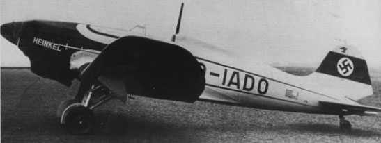
According to his story, the German Reichsluftfahrtministerium RLM (Ministry of Aviation) appointed a young aircraft design engineer and pilot, Rudolph Schriever, to work at the Heinkel-Rostock design office. In reality, he had no verifiable claims to German military service, relating to aviation or otherwise, and his only known employment was for the US Army as a truck driver after the war. It’s also not quite clear, but in some sources there is a mention of a certain Otto Habermohl, supposedly also involved from the start. Not to be beaten out by Schriever, there is not only any evidence for his credentials, but he doesn’t seem to have existed at all.
At that time, different engineers wanted to solve the issue of reducing the space needed to launch and recover aircraft. One solution was to launch an aircraft directly, and vertically into the sky. In this case, such aircraft would not need a long runway and instead could take to the sky from a single launching point. But this concept, while tested over the years, was never successfully implemented during the war.
Schriever claims to have approached this problem with a somewhat unusual solution. He made plans using a disc-shaped aircraft powered by jet engines using the so-called Coanda effect. This effect was named after the Romanian Henri Marie Coanda, an aerodynamic engineer. He discovered that when using a jet stream that is applied tangentially against a convex surface it creates a lift force that could be further increased by circulation. Schiriever claimed to have presented his idea to Ernst Heinkel, who was said to have liked the concept. This supposedly led to the start of work on a small prototype. He claims that after some work, the prototype was completed in early 1941. This prototype received the simple V1 designation without any prefix for the aircraft type. This should not be confused with the V1 flying bomb, as the V stands for Versuchs (experimental or trial model) which was quite commonly used by the Germans especially in the aviation industry to describe experimental or pre-production models. This prototype supposedly consisted of a disc-shaped wing design powered by an electrical rotary fan, no power source is given.
In 1942, this prototype was allegedly flight tested. No precise information about its overall performance exists. The assembly of this prototype named V2 was said to have begun in nearly 1943. By that point, Schriever claimed that some design work was moved from Germany to occupied Czechoslovakia. Škoda factories near Prague are assumed to have provided assistance to this project, though he did not specify in his testimony. A few other companies were also mentioned to be to some extent involved in this project, this includes Junkers, Wilhelm Gustloff, and Kieler Leichtbau. The fate of the V2 prototype is not clear.
The testing of the Schriever flying disc was supposedly observed by a group of some 25 eyewitnesses from the Flight school which was stationed near this airfield. One of these eyewitnesses gave testimony to a German aeronautical magazine Flugzeug in 1987. The truth of these claims cannot be completely verified with certainty. If we consider the fact that more than 40 years have passed since this incident to the moment they gave the interview. They reportedly saw a strange disc-shaped aircraft. This aircraft was described as disc-shaped with an estimated diameter between 5 to 6 m with the height of an average man. They also reported that it had an aluminum color. And that while being on the ground held in position by four landing gear legs. It managed to reach a flight of around 300 m of distance at 1 m of height. In the event the witness was not being intentionally misleading, it is likely they saw a helicopter being tested, several designs of which were researched and built during the war.
This piece of equipment is often mentioned to be the Rudolph Schriever demonstrator for the whole concept.It shares a notable resemblance to a torque converter. Source: B.Rose and T. Buttler Secret project Flying Saucer Aircraft
Name of the project
Beside the names given to the prototypes, this whole project appears to not have received any official designation, which was somewhat odd. It is often simply referred to as the Heinkel-BMW or by its name of the inventor Schriever, or even as the Schriever-Habermohl flying disc. Also sometimes it is also referred to as Flugkreisel (Flying top). This article will use the Heinkel-BMW flying disc designation for the sake of simplicity only.
Further Work
By 1944, the whole team that worked on this project was supposedly moved to Czechoslovakia. The entire personnel were not stationed at one facility but instead relocated to various small cities in that occupied country. Allegedly, this was done to avoid any of them being killed in the Allied bombing raids. The main base of operation was said to be the Praha-Kbely Airfield. According to Schriever, by this time, other aircraft design engineers began joining the program. One of them was SS Lieutenant Helmut Zborowski who was then appointed commander of this base. Given his position, Helmut would be most likely directly involved in the project. Others included Dr. Richard Miethe who may have been involved in the German rocket development. He may have been involved in the Peenemunde rocket research center, but his work there was never verified and so far no connection has been proven. Lastly, there was Klaus Habermohl and surprisingly an Italian, Dr. Giuseppe Belluzzo, who specialized in the work of turbines. The involvement of these two in the supposed project is unclear. Dr. Giuseppe Belluzzo claimed after the war that he was involved in the disc-shaped aircraft project but there is no proof of this. Klaus Habermohl is another strange person that allegedly worked on this project. What is bizarre is that no actual proof was ever found that this was a real person that existed. Lastly, the role of Joseph Andreas Epp, who was an engineer, was a supposed consultant to the Heinkel-BMW flying disc program. After the war, he claimed to have greatly influenced the German disc-shaped aircraft project, but if this is true, or was just an attempt to gain fame are unknown, the latter option seems more possible.
Schierver claimed that, together this team decided to proceed and built a third,even larger aircraft. The necessary component for the aircraft was to be supplied by Heinkel while Bayerische Motoren Werke AG – BMW was to have been responsible for providing the necessary engines. During the construction of the V3 prototype, one member of the team proposed using an experimental radial flow gas turbine engine which was adopted. The V3 was said to have been completed in the autumn of 1944. It was said to be almost double the size of the previous prototype with a diameter ranging from 12.2 to 15.1 m. No specific model of jet engine was mentioned. Supposedly, this aircraft was capable of achieving subsonic speed and could take off vertically.
Alleged drawing of the V3 prototype, note there are a few slightly different drawings of this alleged prototype. Source: www.nevingtonwarmuseum.com
As the war was by this point obviously lost, the Germans tried to delay the inevitable, and out of desperation, the SS became more involved in Wunderwaffe projects. This flying disc was said to be one of them, with their supposed involvement helping to add another layer of esotericism. Supposedly, soon the new V7 prototype was under construction. The fate of the V4, V5, and V6 prototypes is unknown. The last prototype, the V7 was reportedly designed to be larger than its predecessor by having a diameter of 18.3 to 21.3 m. This prototype was to be powered by gas turbine engines, from the start. At some point the work on the prototype was supposedly taken over by Richard Miethe.
Technical characteristics
Given the general obscurity and poor source materials, the precise construction of this bizarre aircraft is unknown. The available information should be regarded as illegitimate as it is technically incorrect, extremely inconsistent, and often fantastical.
The aircraft itself was envisioned as a circular-rotary wing design likely made of metal and powered by several smaller jet engines. It consisted of a centrally positioned crew cabin, which was surrounded by a large rotary wing assembly, resembling a huge fan. These were surrounded by a huge likely metal ring. What holds this ring in place is not clear according to a few drawings of it that exist.
The V7 had a diameter of 18.3 to 21.3 m. To provide stability it is often suggested that this aircraft received a stabilizing fin added close to the central cockpit. The central cockpit appears to be hemispherical and was fully glazed, providing the crew with a good upper all-around view. The lower view would be greatly restricted by the large rotary wing and present extreme difficulty in landing. How they would resolve this issue is not clear. It is possible that at the bottom of the cockpit, additional windows were to have been added. The crew consisted of two to three crew members whose roles were not specified.
Beneath the large rotary wings, at least four jet engines were to be used to power the whole assembly. These provided lift during take-off and landing. Allegedly, horizontal flight could be achieved by adding additional engines possibly connected to the lower part of the cockpit unit. Several different possibilities could have been used for this project. Ranging from Jumo 004, Jumo 211/b, BMW 003 engines, Walter HWK109 rocket engine, or the Argus pulsejet. Its alleged maximum speed achieved was 1,200 km/h or up to 2,000 km/h at a height of 12,400 m. Given its nature, and that none of the engines would have sufficient performance for supersonic flight, both numbers seem unrealistic, to say the least. Even in Rudolph Schriever’s own testimony after the war, he claimed that the prototype only managed to achieve some basic flights. There is no record that any kind of armament was tested on this aircraft.
The Fate of the Project
Like most parts of this aircraft, its final fate is unknown. Hard to verify, and often absurd claims, mention that it climbed to heights of 12.200 m or managed to reach supersonic speed. Given that it was supposedly in its early development phase when the previously mentioned test flight was made, it is dubious that such a flight was possible even with all of the other issues.
The V7 was said to have been destroyed by the Germans to prevent its capture. Or the Germans failed in this and the Soviets managed to capture it, with no evidence existing in either case. There was also said to be a V8 prototype that was under construction by the war’s end. Another interesting but unconfirmed information is that some members of the team who worked on this flying disc including Richard Miethe actually managed to surrender to the Western Allies. This seems unlikely and was possibly fabricated by Miethe, who was known to have been involved in some different conspiracy theories, so his background is also not verifiable.
The alleged photograph was taken by Joseph Andreas Epp while he was driving toward the Prag airport in (possibly August) 1944. The part of the picture to the right is the same photograph that just increased in size and focused on the aircraft itself. Source: H. Stevens, Hitler Flying Saucers
Ironically, the Germans actually managed to develop and built in small series a rocket-propelled VTOL aircraft, the Ba 349. While quite an unusual design, it was a real, and more practical aircraft in contrast to fictitious flying disc projects. By the time it was flight tested in March 1945, it proved to be a failure.
The experimental and unusual rocked-powered Ba 349 Source: Wiki
Production
After the war, Joseph Andreas Epp claimed that at least 15 various prototypes were built and tested by the Germans. This number also includes another similar project that runs parallel to the alleged Heinkel-BMW project.
V1 – Small prototype model
V2 – Second prototype whose fate is unknown
V3 – Tested in late 1944
V4-6 – Possibly paper projects
V7 – Larger fully operational prototype
V8 – Alleged improved V7 prototype
Is the whole story actually True?
Not surprisingly the entire story about Rudolph Schriever’s work is in all likelihood, a complete fabrication. Author, G. Rendall (UFOs Before Roswell) gives a quite detailed account of the Schriever’s involvement, or better said, lack thereof in the German flying disc program.
The connection between Schriever and the Luftwaffe is not clear. While he is often described as having the title Flugkapitan (Flight Captain) this was not an official military rank but instead an honorary title given to civilian test pilots for their service. This usually includes testing a prototype aircraft and testing newly built planes. Schriever, allegedly thanks to his idea of a flying disc, and pilot skill was said to be summoned to Heinkel. In reality, there is no evidence to support this, neither him being an engineer nor a test pilot. His first public appearance and general mention of his flying disc project occurred when he gave an interview to the Der Spiegel news magazine on the 30th of March 1950.
Schriever may have been influenced to come up with his story by the Italian post-war flying disc stories. In the late 1940s Italian engineers showed great interest in designing similar aircraft. One engineer Francesco de Beaumont proposed a disk-shaped aircraft design powered by four jet engines. Another engineer Giuseppe Belluzzo in his own story given to the magazine Il Giornale d’Italia, was he mentioned Italian and German flying disc development.
Francesco de Beaumont proposed a disk-shaped aircraft proposal. Source: B.Rose and T. Buttler Secret project Flying Saucer AircraftA drawing of the Rudolph Schriever flying disc was published in the German newspaper Der Spiegel in March 1950 Source: H. Stevens, Hitler Flying Saucers
In any case, according to Schriever’s interview, he allegedly became involved in the flying disc program in 1942. Quite interesting is the fact that according to Schriever’s own words, this aircraft was successfully flight-tested. He continued to work on this project up to the end of the war when he had to flee with the whole documentation and plans. He set up a small workshop and the documents were stored there. In 1948 he claimed that they had been stolen by an unspecified foreign agency and never found. Despite claiming to be involved in the secret flying disc program as an engineer, Schriever after the war worked as a simple truck driver. As there is no proof of the Heinkel-BMW flying disc, the whole story seems like a fabrication invented by Schriever. As in his later interview, he claimed to be involved in other projects; it is likely that he was seeking attention possibly from the Allies or simply just bored during a time when Germany was undergoing a slow, painful recovery. To add to the likelihood of the latter, at that time German engineers were highly in demand by the Allies and the Soviets. The US army even organized special operations to bring many German scientists to America, yet Schriver’s claims of the disc aircraft were completely ignored. If being recruited was Schriever’s intention, he failed in that regard. In the end, Schriever’s story ended with his death in 1953, as reported by the German Newspaper, Deutsche Illustrierte
The Real German Circular-wing aircraft
As it is often the case, the reality is often quite disappointing for those who believe in the extraterrestrial and esoteric origins of German flying source projects. Likely the only circular-wing design that reached some operational level was the Arthur Sack Sack AS-6. While even this aircraft had a rather obscure history, it is known that one prototype was completed and tested. Given that this was mostly a one-man project built using salvaged components, it should not come as a surprise that it led nowhere. During testing, the aircraft failed to take off and after a number of improvements, attempts to fly the aircraft were eventually discarded. The only prototype would be destroyed in an Allied bombing raid. The Horten Ho 229 could technically also be classified as a flying disc aircraft, though by any technical definition, it is a flying wing. Despite some effort put into its development, it remained at the prototype stage. There were many other projects but few went beyond a mock-up stage.
While Arthur Sack’s work was never implemented in mass production, his unusual design was often mistakenly taken as some advanced and secret German World War II project, which ironically, it never was. Source: all-aero.comThe unusual Sack AS-6 circular-wing aircraft. Source: alkeeins.blogspot.comFew prototypes of the unusual Horten Ho 229 were built and tested during the end of the war. Source: www.ww2-weapons.comFocke-Wulf wooden mock-up of a VTOL aircraft that has some resemblance with a flying disc. Source: B.Rose and T. Buttler Secret project Flying Saucer Aircraft
Conclusion
Based on the few available information what conclusion could be made regarding this unusual design? Given its supposed secrecy and some element of Wunderwaffe allure, there is no doubt that the project is by all indications, fictional. Given the fact that the Germans allegedly spent years developing such aircraft but did not advance beyond the prototype stage, probably an indicator that the whole concept was likely flawed if it existed in the first place.
In the case of Rudolph Schriever’s work, it is quite certain that his entire involvement in such design was purely made-up after the war. Why he would do so is unclear. It is possible that he tried to get the attention of the Allies. In this regard, he failed, as the Allies probably saw,if they ever bothered in the first place, that the whole story was fake and invented from the start. It is much more likely that Rudolph Schriever simply wanted to do a publicity stunt, as he was probably extremely bored being a truck driver in post-war Germany. In the end, it’s likely that Rudolph Schriever never suspected that his story would have gone so far, being propelled by the flying saucer craze of the 1950s.
Alleged Heinkel-BMW V7 Specifications
Wingspans
18.3 to 21.3 m
Engine
Multiple unspecified jet engines
Maximum Speed
1.200 to 2.000 km/h / 745 to 1240 mph
Maximum Service Ceiling
12.400 m
Crew
2 to 3
Armament
None
Illustration
Artist impersonation of the Heinkel-BMW Flying disc
Credits
Article written by Marko P.
Edited by Henry H.
Ported by Henry H.
Illustrated by Medicman 11
Source:
D. Nesić (2008) Naoružanje Drugog Svetsko Rata-Nemačka. Beograd.
R. Ford (2000) German Secret Weapons of WWII, MBI
B.Rose and T. Buttler (2006) Secret project Flying Saucer Aircraft, Midland
J. R. Smith and A. L. Kay (1972) German Aircraft of the WW2, Putnam
H. Stevens, Hitler Flying Saucers. Adventures Unlimited Press
M. Fitzgerald (2018) Hitler Secret Weapons Of Mass Destruction, Arcturus
G. Rendall (2021) UfOs Before Roswell, Graeme Rendall
Nazi Germany (1935)
Fighter Aircraft– 20 to 22 Bf 109A and 341 Bf 109B Built
When the Nazis came to power in Germany during the early 1930’s they sought to modernize their armed forces with more modern military equipment. The founding of a new air force, the Luftwaffe as it was known in Germany, was one of the main priorities of the new regime. Massive resources were channeled into the construction of a great number of airfields and other forms of infrastructure necessary for the air force. In addition, many new and thoroughly developed military aircraft designs were requested. Among these new designs was the Bf 109, which would go on to later become the most widely produced fighter aircraft in the world.
The Bf 109B (R. Jackson Messerschmitt Bf 109 A-D series)
Rise of the Luftwaffe
After the collapse of the German Empire following their defeat in the First World War, the Allies prohibited the development of many new military technologies, including aircraft. The Germans bypassed this prohibition by focusing on developing gliders which provided necessary initial work in aircraft development and crew training. Another solution was to develop civil aircraft that could be relatively quickly rebuilt and modified for military use. The efforts to hide these developments were finally discarded when the Nazis came to power in 1933. One of the first steps that they undertook was to openly reject the terms of the Treaty of Versailles that prohibited the Germans to expand their army and develop new military technologies.
The founding of the Luftwaffe was seen as a huge military priority among Nazi officials. The Luftwaffe would then begin a massive reorganization and expansion project that would see it expand into a formidable fighting force. Much of the Luftwaffe’s attention and energy during this period was focused on developing a new fighter aircraft to replace the then obsolescent Ar 68 and He 51 biplanes. For this reason, in 1934 the Reichsluftfahrtministerium RLM (German Air Ministry) issued a competition for a new and modern fighter plane that could reach speeds of 400 km/h. For this competition, four companies were initially contacted including Arado, Focke-Wulf, and Heinkel. Besides them was a rather small and less-known manufacturer, Bayerische Flugzeugwerke BFW (Bavarian Aircraft Works,) which was under the leadership of Willy Messerschmitt. Despite lacking the experience of their contemporaries in military aviation designs, this small company despite its inexperience would go on to win the contract and build what would become Germany’s then-most modern combat aircraft
The man behind the design
Wilhelm Emil ‘Willy’ Messerschmitt was from his early years interested in aviation. When he was 13, he met Friedrich Harth who was an enthusiast and a pioneering glider designer. He would become a mentor and help Messerschmitt develop his passion for building gliders, together designing and building several gliders. When the First World War broke out in 1914, Harth was drafted into the Army, and in 1917 Messerschmitt would follow. Fortunately for both of them, however, they were stationed at the same flight training school near Munich and were thus able to continue their work. Both of them survived the war and went back to doing what they both loved: designing and building gliders. As gliding was something that became highly popular in Germany after the war, Messerschmitt undertook further education by enrolling in Munich Technical College. With this knowledge, Messerschmitt managed to design and build his first glider in 1921, which he designated simply as S9. After gathering sufficient financial resources, Messerschmitt and Harth together opened a flying school in 1922. This did not last long, however, and the following year disagreements between Messerschmitt and Harth arose.
Messerschmitt then decided to work on his own and opened a small aviation company which he named Flugzeugbau Messerschmitt. His first proper aircraft design was the M17. It was a small all-wood, high-wing, sport aircraft powered by a British Bristol 29 hp engine. This aircraft was quite successful and even managed a 14-hour flight from Bamberg to Rome in 1926. The pilot was a World War One veteran Theodor Croneiss. A little-known fact, this was actually the first flight of such a small aircraft over the Alps ever attempted successfully. The M17 would later be lost in an accident when Messerschmitt himself was learning how to fly an aircraft. He crashed, losing the aircraft but surviving the hard landing, after which Messerschmitt spent some time in hospital. This did not greatly affect Messerschmitt’s new company as his next design M18 also proved to have good overall performance. Now in partnership with Croneiss, they managed to make a deal with Lufthansa, a German civil airline, to use the M18 for passenger transport.
The high wing, sport aircraft M17, was the first Messerschmitt aircraft design. (www.histaviation.com)
Messerschmitt’s company received a number of production orders for their M18 aircraft. However, Messerschmitt lacked the money, resources, and production capabilities to actually deliver these aircraft. At some point, he came in contact with the Bavarian government in hope of finding a solution to his problem. He got an answer, that the Bavarian government was willing to help with one condition, Messerschmitt would have to merge his own company with the Bayerische Flugzeugwerke BFW. This company itself was in the midst of a huge financial crisis but possessed a great number of skilled workers and equipment that could greatly help Messerschmitt in his future work. While both companies would be technically independent, Messerschmitt was to give first production rights for any of his new designs to BFW. BFW on the other hand would provide the necessary manpower and equipment. Messerschmitt agreed to this condition and was positioned as chief designer of both companies. Representation of the company was relocated from Bamberg to Ausburg.
In 1928 Messerschmitt focused his work on a civil design intended for transporting passengers. His next design was the 10-passenger transport aircraft designated M20. During a flight test, part of the wing fabric cover peeled away, and pilot Hans Hackman possibly in a panic decided to bail out at a height of 76 m. His parachute failed to open properly and he died. This led to the cancellation of production orders for the M20 by Lufthansa. Messerschmitt developed an improved second M20 prototype which was presented to, and tested by Lufthansa officials. After an evaluation, the aircraft was deemed safe and a production order for 12 improved M20. However, tragedy would strike in two serious accidents involving the M20 aircraft, in which 10 people were killed. The first accident happened near Dresden in October 1930, where two pilots and six crew members were killed. The second occurred in April of the next year, with the death of both pilots. To make matters even worse, German Army officers were among the casualties. This affected Messerschmitt’s further work, who despite developing more aircraft designs failed to gain many production orders for them. While his own company did not suffer much, BFW was not so lucky and was forced into bankruptcy in 1931. In the next few years, Messerschmitt’s work was relatively stable as he saw some success selling his aircraft aboard. With better financing, he managed to acquire sufficient funds to reinstate BFW in May of 1933. The name was changed to BFW AG, a publicly-traded company. Unfortunately for Messerschmitt, a newly appointed Secretary of State for Air, Erhard Milch, opposed the idea of BFW operating under Messerschmitt. Erhard Milch’s hatred for Messerschmitt was personal, as the test pilot who flew on the doomed M20 prototype was his friend. He never forgave Messerschmitt who he deemed responsible for the accident. He forced BFW AG to accept production orders for Heinkel aircraft designs. This was also partly done to provide adequate financial resources so that the company could operate successfully.
Despite this distrust by Nazi officials, Messerschmitt was contacted in the summer of 1933 by the RLM to design a sports aircraft to represent Germany on the Challenge de Tourisme Internationale. Seeing a new opportunity Messerschmitt took great care in fulfilling this order. His ultimate design would be the highly successful Bf 108 (initially designated M37.) This aircraft would be crucial in the later stages of Bf 109 development. With the success of the Bf 108, Messerschmitt managed to gain support from some top Luftwaffe officials. One of these was the newly appointed Hermann Goring who replaced Erhard Milch in the position of commander-in-chief of the Luftwaffe. While there were still some who wanted the Bf 108 to be canceled, with the support of Hermann Goring they could do little about it.
The highly successful Bf 108. (www.luftwaffephotos.com)
A new fighter
In March of 1933 RLM issued a document (designated L.A. 1432/33) that laid the foundations for the development of the future German fighter aircraft. In it a shortlist of general characteristics that this aircraft should meet was given. It was to be designed as a single-seat fighter that must be able to reach speeds of at least 400 km/h at a height of 6 km. In addition, that height had to be reached in no more than 17 minutes. The maximum service ceiling was set at 10 km. Armament was to consist of either two machine guns each supplied with 1,000 rounds of ammunition or one cannon with 100 rounds of ammunition.
In February 1934 this document was given to three aircraft manufacturers, with these being Arado Heinkel and BFW AG. The last to enter the competition was Focke-Wulf who received this document in September of 1934. While not completely clear as some sources suggest, Messerschmitt and the BFW AG were not initially contacted but were later included in this competition. Realizing this competition as a great opportunity, Messerschmitt gathered the best team he could find. Some of these included the former Arado fighter designer Walther Rethal, who became Messerschmitt’s deputy. Another prominent figure was Robert Lusser who took a great part in the Bf 108 development. He would also later play a great part in the future Bf 110 aircraft design.
According to RLM conditions, all interested companies were to provide a working prototype that was to be tested before a final decision was to be made. Arado and Focke-Wulf completed their prototypes, the Ar 80 and Fw 159, by the end of 1934. Heinkel and Messerschmitt’s prototypes took a bit longer to complete. Messerschmitt and his team set a simple but ambitious plan. Their aircraft would be simple, cheap, and possess lightweight overall construction. It was to be powered by the strongest engine they could get their hands on. Work on this new fighter began in March 1934, at this early stage, the project was designated as P.1034 (while sometimes in the sources it is also mentioned as Bf 109a). A simple airframe mock-up was completed shortly in May the same year, but the work on a more complex and detailed mock-up took some time. By January 1935 it was finally ready. The engine chosen for it was the Jumo 210A. As this engine was not yet available, the license-built 583 hp Rolls-Royce Kestrel engine was used temporarily instead. Ironically this engine was available thanks to the good business relationship between Heinkel and the British Rolls Royce motor company. Thanks to this cooperation the Germans managed to purchase a number of these engines.
The first prototype named Bf 109 V1 (registered as D-IABI) was flight tested by Hans Dietrich Knoetzsch at the end of May 1935. The first flight was successful as no problems were identified with the design. While later prototypes would be tested with a weapon installation, the V1 was not outfitted with any armament.
The Bf 109 V1 (registered as D-IABI). (www.asisbiz.com)
Messerschmitt designation
Before we continue, it is important to clarify the precise designation of this aircraft. Sometimes it is referred to as Me 109 (or as Me-109). While technically speaking this is not completely incorrect given that it was designed by Messerschmitt and his team. The Bf stands for Bayerische Flugzeugwerke, the company which constructed the aircraft. While the 109 has no specific meaning, it was just next in the line after the 108 design.
In 1938 this company would be renamed Messerschmitt AG and all future designs from this point on would receive the prefix ‘Me’. The older designs including the 108 and 109 would retain the Bf prefix during the war. It is worth pointing out that both the Bf and Me designation was used in Messerschmitt’s own archives. In German service prior to and during the war, it was not uncommon to see both designations being used. So using either of these two designations would be historically accurate, this article would use the Bf 109 designation for sake of simplicity but also due to the fact that in most sources this designation was used.
The Bf 109 trials
As no major issue was noted in its design, the Bf 109 V1 was to be transported to the test centers located at Rechlin and Travemunde starting in October 1935. Here, together with all competitor designs, they would be subjected to a series of evaluations and tests. The Ar 80 and Fw 159 proved inadequate almost from the start after many mechanical breakdowns and even crashes, which ultimately led to both being rejected. The He 112 and Bf 109 on the other hand proved to be more promising designs. The Bf 109 had a somewhat bumpy start as the Rechlin airfield was unfinished and had a rough runway. During a landing, one of the Bf 109’s landing gear collapsed. Despite what appeared at first glance to be catastrophic damage, turned out to be only minor.
The He 112 V1, was used for the trials held at Rechlin and Travemunde. (www.luftwaffephotos.com)The Bf 109V1 was damaged during a failed landing. (R. Jackson Messerschmitt Bf 109 A-D series)
The second prototype was completed and tested by the end of 1935. The V2 (D-IILU or D-IUDE according to some sources) was powered by a domestically developed 680 hp Jumo 210A engine. It was moved to Travemunde for evaluation and testing in February 1936. The V2 was put into a series of test flights where it showed superb flying performance, in contrast to the other competitors. Unfortunately, during one test flight undertaken in April, part of the pilot’s canopy peeled away, forcing the pilot to make an emergency landing. A decision was made to not repair this prototype but instead to use its fuselage for ground testing and experimentation.
That same month that the V2 was damaged, the V3 (D-IQQY) was flight tested. This prototype served as the test aircraft for the installation of offensive armament. There is a disagreement between sources, as J. R. Beaman and J. L. Campbell mentioned that the armament was actually tested on the V2 aircraft. Regardless of which prototype was first armed, it possessed two 7.92 mm MG 17 machine guns. These were placed above the engine, close to the cockpit. The engine was once again changed, this time with the installation of the even more powerful 700 hp Jumo 210C. Another experimental feature was the installation of a FuG 7 radio unit. This necessitated adding a triple wire antenna, which was connected to the top of the fin, and the edges of the stabilizers to the cockpit. This aircraft would be extensively used for testing, and would later serve as the basis for the first production version. Later prototypes were used to test various additional equipment and weapon installations. For example, prototypes V4 to V7 were used to test various different armament arrangements. The V5 was used to test the installation of an automatic reload and firing system, among other features.
The V3 in a flight. (en.topwar.ru)
During the initial evaluation flights carried out on both the Bf 109 and He 112, the latter was favored by many test pilots. Heinkel at that time was among the largest and most well-known German aviation manufacturers. It supplied the new Luftwaffe with a series of aircraft, and thus was well connected to RLM top officials. Further examination of the Bf 109 showed that the aircraft had several persistent issues. The most serious problems were the Bf 109’s tendency to widely swing to the left during landing and take-off. Another major issue was the design of landing gear, which was too narrow and generally weak. This in turn would often lead to crash landings. In retrospect, these two problems would never be fully resolved, but with sufficient training and experience, these problems could be overcome by the pilots. Other complaints included the limited visibility due to the canopy’s small design. The cockpit interior was also regarded as too cramped. The Bf 109 was also notorious for its high wing loading, which was pointed out by the test pilots.
Most of these complaints do not necessarily indicate a flawed design. We must take into account that the test pilots were mostly experienced in older biplanes. This new single-wing fighter concept was completely strange to them. For example, the biplanes had a simple and open cockpit, so complaints regarding the Bf 109 cockpit design represented a refusal to adapt to newer technologies rather than a bad design.
During the series of test flights, the performance of the two competitors was quite similar, with some minor advantages between them. In the case of the Bf 109, it was slightly faster, while the He 112 had lower wing loading. In addition, the He 112 had a better-designed and safer landing gear assembly. As the He 112 had to be constantly modified in order to keep pace with the Bf 109, the RLM commission was getting somewhat frustrated. Despite Heinkel’s connections and experience in designing aircraft, the Bf 109 was simply more appealing to the RLM commission, given that it was simpler, faster, and could be put into production relatively quickly. At that time the Germans were informed by the Abwehr intelligence service that the British were developing and preparing for the production of the new Spitfire. RLM officials were simply not willing to risk taking a chance on an aircraft design that could not quickly be put into production. Thus the Bf 109 was seen as the better choice under the circumstances.
Technical characteristics
The Bf 109 was a low-wing, all-metal construction, single-seat fighter. In order to keep the production of this aircraft as simple as possible, Messerschmitt engineers decided to develop a monocoque fuselage that was divided into two halves. These halves would be placed together and connected using simple flush rivets, thus creating a simple base on which remaining components, like the engine, wings, and instruments would be installed.
The central part of the fuselage was designed to be especially robust and strong. Thanks to this, it offered the aircraft exceptional structural integrity. It also provided additional protection during emergency crash landings. The fuselage itself and the remainder of the aircraft were covered with standard duralumin skin.
Its wings also had an unusual overall design. In order to provide room for the retracting landing gear, Messerschmitt intentionally used only a single wing spar which was positioned quite to the rear of the wing. This spar had to be sufficiently strong to withstand the load forces that acted on the wings during flight. The wings were connected to the fuselage by four strong bolts. This design enables the wings to have a rather simple overall construction with the added benefit of being cheap to produce. During the Bf 109 later service life, the damaged wings could be simply replaced with others on hand. The wings were also very thin, which provided the aircraft with better overall control at lower speeds but also reduced drag which in turn increased the overall maximum speed. At the wing’s leading edge were slats that automatically opened to provide better handling during maneuvers at lower speeds. This had a secondary purpose to greatly help the pilot during landing. The tail unit of the Bf 109 was a conventional design and was also built using metal components. It consists of a fin with a rudder, and two vertical stabilizers each equipped with an elevator.
The cockpit was placed in the center of the fuselage. It was a fully enclosed compartment that was riveted to the fuselage. The Bf 109 cockpit itself was quite cramped. Most of the available space was allocated to the control stick. Left and right of the pilot were two smaller control panels with the main instrumental panel being placed in front of him. While the side control panels were a bit small, their overall design was more or less the standard arrangement used on other aircraft. The front instrumental panel contained various equipment such as the compass, and an artificial horizon indicator. Messerschmitt engineers also added an ammunition counter, which was somewhat unusual on German fighters. Another innovative feature was the installation of a FuG 7 radio unit. In front of the cockpit, a firewall was positioned to shield the pilot in case of an engine fire.
The overall framework for the canopy was fairly small, but despite this provided decent all-around visibility for the pilot. Its main drawback was limited forward visibility during take-off. The canopy opened outwards to the right. This was a major issue as it could not be open during the flight. To overcome this, it was designed to be relatively easily jettisoned. In case of emergency, the pilot would actuate a lever positioned in the rear. It was connected to two high-tension springs. When activated, the lever would release the two springs, which in turn released the canopy, which would then simply fly away due to airflow.
The Bf 109 canopy opens outwards to the right, this causes problems as it was unable to be open during the ground drive or in flight. (R. Jackson Messerschmitt Bf 109 A-D series)
When designing the Bf 109 great care was taken for it to have a simple design. This is especially true for the engine compartment. The engine was easily accessible by simply removing a series of panels. The engine was mounted on two long ‘Y’ shaped metal bars and held in place by two quick-release screws. The necessary electrical wires were connected to a junction box which was placed to the rear of the engine. All parts inside the engine compartment were easily accessible and thus could be replaced in a short period of time. The Bf 109 “L” shaped fuel tank was located aft of the pilot’s seat and slightly underneath it. It too had easy access by simply removing a cover located inside the center of the wing. The total fuel capacity was 250 liters.
Once the Bf 109 was accepted for service, a small production run of the Bf 109B-0 was completed. It was powered by a 610 hp Jumo 210B, and served mainly to finalize the later production version. The Bf 109B-1 was powered by a 635 hp Jumo 210D engine and had a fixed-pitch two-blade wooden propeller. Later during the production, it would be replaced with a new all-metal two-bladed variable pitch propeller. This engine was equipped with a two-stage supercharger. The maximum speed achieved with this engine at the height of 3,350 meters (11,000 ft) was 450 km/h (280 mph). The engine oil cooler, which was initially placed close to the radiator assembly, would be repositioned under the right wing.
The Bf 109 had a simple engine housing that could be easily removed if the engine needed to be removed. (R. Cross, G. Scarborough, and H. J. Ebert (Messerschmitt Bf 109 Versions B-E)
The Bf 109 possessed quite an unusual landing gear arrangement. The landing gear was mainly connected to the lower center base of the fuselage, which meant that the majority of the weight of the aircraft would be centered at this point. The two landing gear struts retracted outward towards the wings. The negative side of this design was that the Bf 109, due to its rather narrow wheel track, could be quite difficult to control during taxiing. Messerschmitt engineers tried to resolve this issue by increasing the span of the two wheels. This actually complicated the matter as it necessitated that the two wheels be put at an angle. In turn, this created a weak point where the wheels were connected to the gear strut, which could easily break during a harsh landing. This also caused problems with the Bf 109 tendency to swing to the side prior to take-off. When the pilot was making corrections to keep the aircraft headed straight, excessive force could be applied to the pivot point of the landing gear leg, which sometimes cracked.
The Bf 109 possessed a quite unusual landing gear that retracted outward towards the wings. (www.worldwarphotos.info)
The first series of the Bf 109 were only lightly armed, with two 7.92 mm electrically primed MG 17 machine guns. While this may seem like underpowered armament, we must not forget that in the period between the wars, mounting larger caliber guns in fighters was rare. Larger calibers at this time used were usually 12.7 mm. The two machine guns were placed in the upper fuselage, just forward of the cockpit. The port-side machine gun was slightly more forward than the starboard. This was done to provide more space for ammunition magazines. These were fully synchronized to be able to fire through the propellers without damaging them. In the early stages, the ammunition load consisted of 500 rounds for each machine gun, but this was later increased to 1,000 rounds.
The MG 17 was used as the main armament of the early Bf 109’s. (airpages.ru)
However, the double MG 17 layout was eventually deemed somewhat weak, so Messerschmitt was instructed to increase the offensive firepower. As Messerschmitt initially did not want to add any armament in the wings, another solution was needed. The installation of a third machine gun inside the centerline of the engine block was tested. While this would be initially adopted, this installation proved to be problematic mostly due to overheating and jamming problems. So this machine gun was often not installed and removed on those aircraft that had it. A possible installation of a 20 mm cannon in its place was also tested. This was the 20 mm MG FF cannon, which was in fact a license-built version of the Swiss Oerlikon cannon. While it was tested on a few prototypes, it too proved unusable due to excessive vibration. On the other hand, the installation of two non-synchronized machine guns in the wings proved to be more promising, and this was implemented and installed on the later Bf 109E. For the reflector gunsight, a Revi C/12C type was used.
Main armament side view. (Bf 109B LDv.228-1 Document)The left machine gun was slightly moved forward in order to avoid problems with ammunition supply. (Bf 109B LDv.228-1 Document)
The Bf 109A and B versions
The Bf 109 A version is somewhat of a mystery in the sources. Usually this version, besides a few mentions, is rarely described in the sources. According to Messerschmitt’s own documents, a small series of 20 to at least 22 aircraft of this version were built. It appears that in every aspect, it was the same as the later B version. The only major difference between these two versions was that the A was solely equipped with the two machine guns in the upper engine cowling.
This is probably why most sources barely mentioned the A version, likely lumping them in with the B version. To further complicate matters author D. Nesić mentioned that while version A was planned to enter production, it was abandoned due to its weak armament.
Once the Bf 109 was accepted for service, a small pre-production run of 10 Bf 109B-0 was completed. It was powered by a 610 hp Jumo 210B, and served mainly to finalize the later production version. The Bf 109B-1 was powered by a 635hp Jumo 210D engine. This engine was fitted with a fixed-pitch two-blade wooden propeller. It was armed with three machine guns, with two placed above the engine compartment, and the third fired through the centerline of the engine and propeller hub. During the production run of the B-1, some minor changes were introduced. The three-wire radio antennas were replaced with a single one. To provide better cooling of the machine guns, several vent ports were added. The Bf 109B-1 was then replaced with the Bf 109B-2. The 109B-2 was initially powered by a 640 hp Jumo 210E but was replaced with a stronger 670 hp Jumo 210G. The wooden propeller was upgraded to a new completely metal, variable-pitch, two-bladed propeller.
During early production, three-wire radio antennas were used. These would be replaced with a single one. (www.luftwaffephotos.com)
While at first glance, the infamous Bf 109 seems to be a well-documented aircraft, this is not quite the case. Namely, there are significant differences in the sources regarding the precise designation of the B series. For example sources like R. Jackson (Messerschmitt Bf 109 A-D series) and J. R. Smith and A. L. Kay (German Aircraft of the WW2) divided the B series into three sub-series: the B-0, B-1, and B-2.
On the other hand sources like R. Cross, G. Scarborough and H. J. Ebert (Messerschmitt Bf 109 Versions B-E) mentioned that in the Messerschmitt archives, no evidence for the existence of a B-2 series was found. In addition, while the Jumo 210G may have been tested on the Bf 109B series, there is also little evidence that it was actually installed in them. This is also supported by sources like Lynn R. (Messerschmitt Bf 109 Part-1: Prototype). This particular source indicated that all alleged modifications to the B-2 were actually implemented on the B-1 aircraft.
Early Bf 109 operational use
The Bf 109 was shown to the general public for the first time during the 1936 Olympic Games held in Germany. The following year several Bf 109’s (including the V10, V13, two B-1, and one B-2) participated in the international flying competition held in Zurich, Switzerland, easily winning several awards including fastest dive, climbing, and flew a circuit of the Alps, etc. The event was not without incident, as the Bf 109 V10 had an engine problem, and its pilot Ernst Udet, was forced to crash land it.
In Spain
When the Spanish Civil War broke out in 1936, Francisco Franco, who was the leader of the Nationalists, sent a plea to Adolf Hitler for German aid in providing military equipment including aircraft. At the early stages of the war, nearly all of Spain’s mostly outdated aircraft were in the hands of the Republicans. To make matters worse for Franco nearly all forces loyal to him were stationed in Africa. As the Republicans controlled the Spanish navy, Franco could not move his troops back to Spain safely. Franco was therefore forced to seek foreign aid. Hitler, seeing Spain as a potential ally, was keen on helping Franco and agreed to provide assistance. At the end of July 1936, some 86 aircrew personnel, together with 6 He 51 and 20 Ju 57 were secretly transported to Spain. This air unit would serve as the basis of the so-called German Condor Legion which operated in Spain during the war. The Ju 52 transport aircraft proved instrumental in transporting the Francoist forces to Spain. The operation was a success, but the enemy was quite busy with their own preparations.
On the other side, the Republicans were greatly supported by the Soviets, providing them with some 30 I-15 fighters in late 1936. Additionally, the Republicans operated a number of Soviet SB-2 bombers. The few He 51 fighters of the Condor Legion were outdated and outnumbered by the enemy air force, so a request was made to send additional and more modern aircraft. Seeing an opportunity to test the performance of the Bf 109 in real combat situations, it was agreed to send a few to Spain. One of the first Bf 109 V4 to be sent to Spain was unfortunately damaged in an accident. Several delays later on the 14th of December, the Bf 109 V3 arrived in Spain. These arriving aircraft were initially used for a few weeks for testing and training. Initial evaluation of these early aircraft proved to be more than satisfactory, and additional aircraft of this type was requested. Besides the V3 and V4, the V6 was also sent to Spain. The fate of the V5 is not clear; some sources mentioned (like R. Jackson) that it was also used in the Spanish Theater. Lynn R. (Messerschmitt Bf 109 Part-1: Prototype) on the other hand informs us that the V5 was used during 1937 for weapon trials and thus not sent to Spain.
In early 1937 the first of the Bf 109s began to arrive. It is unclear which exact version was first issued for service, these were either version A or B. Author Lynn R. ( Messerschmitt Bf 109 Part-1: Prototype) mentioned that the first aircraft used were of the A version. He indicated that this was the case for several reasons, one of which was the use of only two machine guns. In addition, these were not equipped with the later-developed automatic cycling gun mechanism, which alleviated ammunition jam and misfeed issues. In total, at least 16 aircraft of the early Bf 109 would be sent in this shipment. Sources like R. Jackson (Messerschmitt Bf 109 A-D series) mentioned that only the B version was used in Spain.
During the Spanish Civil war, initially only smaller quantities of Bf 109A and B were available for service. (me109.airwar1946.nl)
In March 1937, with the arrival of the first group of the new Bf 109, two fighter groups were formed. These were the I and II/Jagdgruppe J.88 under the command of Lieutenant Günther Lützow. Interestingly, these aircraft were initially to be given to JG 132 stationed at Döberitz-Elsgrund. Due to the urgent need to reinforce the Condor Legion, JG 132 pilots with the Bf 109 were transported to Spain instead. Besides markings, they also received numerical designations beginning with 6-1, 6-2, and so on. The precise method which was used to determine the numbering designation is not clear. For example, the V3, which arrived second, received the 6-2, and later 6-1 designation. The Bf 109 that served with the Condor Legion received a large black circle on the fuselage for identification. Two additional black circles with a large white “X” were painted on the wings. An additional black X was painted on the rear tail.
The Bf 109 that saw service during the Spanish Civil War could be easily distinguished by their unique markings. Those received a large black circle marking on the fuselage. Two additional black circles with a large white “X” were painted on the wings. An additional black X was painted on the rear tail. ( www.luftwaffephotos.com)
Initially, it was planned that the Germans would act as instructors for their Spanish allies. As the Spanish had problems piloting the newly supplied aircraft, many German instructors would themselves see extensive combat action during the war.
Lützow was also the one who achieved the first kill of the Bf 109B that was used in Spain. He managed to shoot down a Republican I-15 on the 6th of April 1937. Three more victories were achieved during that month. At the end of April, the II.J/88 provided protection for bombers that raided the small town of Guernica. Initially, the few Bf 109 that were available did not have much effect on the war efforts of the Nationalists. The Republicans had nearly 150 modern Soviet fighters and thus had a clear advantage. During the heavy fighting at Madrid in July 1937, the Bf 109 engaged the enemy I-16’s for the first time in the conflict.
In July of 1937, a Bf 109 from the II.J/88, managed to shoot down three SB-2 bombers, one Aero A.101 light bomber, and three I-16. But the J.88 also suffered its first casualty of the war, a Bf 109B which was piloted by Guido Honess was shot down by an I-16 on the 12th of July. On the 17th, another Bf 109 was shot down but the pilot Gotthard Handrick managed to survive. The next day, another Bf 109 was lost but the pilot was only lightly wounded.
In August 1937, the Nationalists launched an offensive toward Republican-held positions around Santander. The heavy fighting that lasted up to October saw extensive use of air forces on both sides. The Nationalists were reinforced with the I.J/88 under the command of Harro Harder. By late October this commander managed to bring down 7 enemy aircraft. At the end of 1937, an incident of note occurred where a Bf 109A piloted by Otto Polenz was forced to land on Republican-held territory. His aircraft was captured almost intact and shipped to the Soviet Union for examination. During the German Invasion of the Soviet Union in 1941, this particular aircraft would be recaptured.
The captured Bf 109A was shipped to the Soviet Union for examination. Ironically it would be recaptured by the Germans in 1941. (Lynn R. (1980) Messerschmitt Bf 109 Part-1: Prototype to ‘E’ Variants, SAM Publication)
On the 16th of December, the Republicans launched an offensive toward the city of Teruel. Given the severe winter, the J.88 was unable to provide air support and the city fell to the Republicans. From late January and early February on, thanks to better weather, the German Bf 109s were once again active. On the 7th of February 1938, Wilhelm Balthasar managed to alone shoot down four SB-2 bombers alone during one flight. He too was forced to a harsh landing having received numerous hits by the bomber’s defensive fire, but Balthasar survived the landing.
By April 1938 the Nationalists realized that a direct attack on Madrid would be almost impossible without heavy casualties, and decided on another approach. They instead focused on the southern parts of Spain. The J.88 too was repositioned there and took on the enemy aircraft. Several Bf 109s were lost during this time, but most of these were either to mechanical breakdowns or pilot errors. For example, on one occasion two Bf 109s collided in midair on the 4th of April. While one pilot was killed, the second managed to escape by using a parachute. The following month saw extensive fighting on the ground and in the air. The Bf 109 pilots, thanks to their better machines and experience, achieved a series of victories over their opponents. On one occasion in late July 1938, three squadrons of Bf 109 took on a group of 40 I-15 and I-16. After a long engagement, the enemy lost six planes, while the Nationalists lost none. The Germans pilots were achieving so many victories that they had to invent excuses in order to not be sent back to Germany. According to official regulations, once a pilot had achieved 5 kills, he was to be replaced by another pilot. This regulation was clearly ignored as pilots like Werner Molders achieved some 14 victories. Other pilots were also very successful, Otto Bertram achieved four victories during August. While Werner Molders scored 8 victories through this period. During 1938, an additional 26 Bf 109B-1 with coded numbers, ranging from 6-19 to 6-45 arrived in Spain.
By early 1939, the Nationalists managed to gain almost complete air supremacy, thus air to air combat became a rare event. The J.88 aircraft were from this point on mostly used for ground attack operations. The last J.88 air victory of the war was achieved on the 5th of March when an I-15 was shot down. Out of some 130 Bf 109s that saw service in Spain, between 20 to 40 aircraft were lost (depending on the source). Not all were lost in air combat, most were lost due to mechanical breakdowns, pilot errors, or hard landings.
While the Republicans would fly in loose formations with any proper tactics, the Germans would employ a so-called Schwarm (swarm) tactic. This basically consisted of using a group of four aircraft, which would fly in a reverse ‘V’ shaped formation, with some 200 meters separating each aircraft. When attacking, these would be divided into two groups of two aircraft. Which were intended to provide each other with cover in the event enemy fighters gave chase.
In German Service
While the Bf 109 was initially used for various tests and participated in sporting events, these aircraft were soon allocated to Luftwaffe units. The first such unit to receive the Bf 109 B-1 was the Jagdgeschwader (fighter squadron) JG 132 in February of 1937, being supplied with 25 aircraft. Due to some delays in production, the second unit equipped with the Bf 109, II./JG 234, was formed nearly nine months later. In early 1938, the production of the Bf 109 was greatly increased which provided a sufficient number of aircraft to equip additional units.
The early Bf 109s were prepared to see potential action during the political crisis regarding the German relationship with Austria and later Czechoslovakia. Even by the end of 1937, the pressure on Austrian politicians was great as the Germans wanted to install a more friendly government. All these political machinations ended in March 1938 when German troops entered Austria without any resistance.
The German request for territories belonging to Czechoslovakia was initially met with fierce resistance from the Western Allies, France, and the United Kingdom. These tensions could have easily cascaded into open war. This particularly caused huge concern in the RLM, as the German Air Force was not yet ready for a war. The situation was so desperate that even some He 112 were accepted for service. In the end, the Western Allies backed down, not willing to go to war, and allowed the Germans to take disputed Czechoslovakian territory.
As the new and improved models of the C and D versions began to be available, the Bf 109B were slowly being allocated to secondary roles, such as training. In this role, some would survive up to 1943. By the time of the invasion of Poland in September, the majority of Bf 109 in use were the D version, with ever-increasing numbers of the new E version. While some Bf 109B were still present in frontline units, their fighting days were over.
Production
For the upcoming Bf 109 production, initially BFW AG was responsible. As it lacked production capabilities given that it was already under contract (made earlier with RLM) to build several other aircraft types, another solution was needed. When BFW AG completed all previously ordered aircraft, it was to focus its production capabilities on the Bf 109.
To increase overall Bf 109 production, other manufacturers were also contracted. Some 175 were built at Erla Maschinenwerk from Leipzig, with 90 more by Fieseler, and only 76 aircraft by BFW. The production run of the Bf 109A lasted from December 1936 to February 1937. In 1937 some 341 Bf 109B would be built.
Production Versions
Bf 109 V – Prototypes series aircraft
Bf 109 A – Proposed production version built in small numbers
Bf 109 B-0 – A small pre-production series
Bf 109 B-1 – Production version
Bf 109 B-2 – Slightly improved B-1 version incorporating a new propeller. Note that the existence of this particular version is disputed in sources.
Surviving Aircraft
Today only one Bf 109B-0 V-10 is known to have survived. Given its rather low production numbers, this is not surprising. It is in a private collection of the “Bayerische Flugzeug Historiker” Oberschleissheim in Munich, Germany.
Conclusion
Despite focusing mainly on civilian aircraft, Messerchmitt and his team of engineers managed to design a fighter that bested all the other well-established manufacturers for Luftwaffe’s new fighter program. The Bf 109 was inexpensive to build and possessed good overall flight capabilities. While a good design, there was plenty of room for improvement, mainly regarding its armament and engine, which would be greatly improved in subsequent iterations.
Me 109B-1 Specifications
Wingspans
9.9 m / 32 ft 4 in
Length
8.7 m / 28 ft 6 in
Height
2.45 m / 8 ft
Wing Area
16.4 m² / 174 ft²
Engine
Jumo 210D
Empty Weight
1,580 kg / 3,483 lbs
Maximum Takeoff Weight
1,955 kg / 4,310 lbs
Maximum Speed
450 km/h / 280 mph
Cruising speed
350 km/h / 220 mph
Range
690 km / 430 miles
Maximum Service Ceiling
8,200 m
Crew
1 pilot
Armament
Initially three 7.92 mm MG 17 machine guns, later changed to four same type machine guns
Illustrations
Credits
Written by Marko P.
Edited by Stan L. Henry H.
Illustrations by Hansclaw
Source
D. Nesić (2008) Naoružanje Drugog Svetsko Rata-Nemačka. Beograd.
D. Monday (2006) The Hamlyn Concise Guide To Axis Aircraft OF World War II, Bounty Books.
R. Jackson (2015) Messerschmitt Bf 109 A-D series, Osprey Publishing
J. R. Smith and A. L. Kay (1972) German Aircraft of the WW2, Putham
R. Cross, G. Scarborough and H. J. Ebert (1972) Messerschmitt Bf 109 Versions B-E Airfix Products LTD.
J. R. Beaman and J. L. Campbell (1980) Messerschmitt Bf 109 in action Part-1, Squadron publication
Lynn R. (1980) Messerschmitt Bf 109 Part-1: Prototype to ‘E’ Variants, SAM Publication
A flight of five No.101 Squadron Overstrands. (Boulton Paul Aircraft Since 1915)
The Boulton Paul P.75 Overstrand was a two-engined biplane that became the RAF’s mainstay bomber aircraft in the early to mid 1930s. The Overstrand was an improvement upon the earlier P.29 Sidestrand biplane bombers after the type recieved several criticisms regarding the frontal gunner position being exposed to the elements on such a high speed aircraft. To amend the complaints, Boulton Paul would design a modified version of the Sidestrand that would use a fully-enclosed powered turret, which would be revolutionary for the time. To test the design, three Sidestrands would be converted into Overstrands. The Overstrand would equip No.101 squadron and 25 newly built Overstrands would be constructed. Aside from mainline service, a number were experimentally modified by Boulton Paul, such as receiving different turret arrangements and more powerful engines. By the time of the Second World War, the aircraft had become obsolete, as new monoplane bombers entered production and replaced it. The type would continually fly in limited numbers for training and auxiliary purposes, but by 1941 would be considered obsolete and grounded.
Boulton & Paul and the Sidestrand
The Boulton & Paul P.29 Sidestrand was a modern and aerodynamic aircraft of the time. But while it was fast it had several glaring flaws, the biggest being the open front turret which exposed the gunner to high speed winds and cold air. (Boulton Paul Aircraft Since 1915)
In the mid 1920s, the Boulton & Aircraft company was beset by hard times. The company was surviving off of small orders for prototype aircraft and was in a rough financial state. The company had, up to this point, focused on creating twin-engine biplane bombers, starting with the Bourges in the First World War and going to their latest of the time, the P.25 Bugle. In late 1925, their savior would be their newest twin bomber design; the P.29 Sidestrand. It was an all-metal, twin-engine biplane bomber with extensive work done into designing its aerodynamic fuselage, creating an innovative and sleek-looking aircraft for the time. Production was soon ordered and 18 were built. This new bomber would populate the No.101 squadron, the only bomber squadron the RAF was operating at the time. Despite its success, a problem began to arise with the forward gunners of the aircraft. The Sidestrand, thanks to its aerodynamic design and powerful Bristol Jupiter engines, was able to achieve a top speed of 140 mph (225 km/h). While this speed made the twin engine bomber quite a fast aircraft for the time, this luxury was not so appreciated by the front gunners of the aircraft, who had no means of protection against the strong slipstream in their open cockpits. The strong winds made aiming the Lewis gun difficult, as it was blown around, and even reports of the propellers being hit by drum magazines thrown from the position were growing to be common. This was not to mention the extreme cold the gunner had to endure as well. Frozen fingers were another common complaint from Sidestrand gunners. While the Sidestrands began to take to the air (and torment their front gunners), Boulton & Paul set to procure more production orders of the type over the 18 that were built, but no further production was ordered, mostly due to the worldwide recession. In the early 1930s, many current fighters of the time were experiencing the same slipstream issues as the Sidestrand was. The Air Ministry put out an order on December 28th, 1932 to seek design reworks that would fix this now commonplace issue with the Sidestrand. While many of the other aircraft would seek simple means, the issue with the gunner position on the Sidestrand was more complex and would require more work put into redesigning the aircraft. Ultimately, Boulton & Paul would decide the answer was a completely covered turret. The company had been working on such a design with their P.70 aircraft concept.
The P.70 was a concept aircraft that was based off the P.64 mailplane and used components of the Sidestrand. While it was never built, it had an innovative enclosed nose turret that the Overstrand would use. (Boulton Paul Aircraft Since 1915)
The P.70 was a twin-engine biplane bomber design based on their earlier P.64 mailplane and incorporated aspects of the Sidestrand. In the nose of the P.70 was a fully enclosed, cylindrical turret that was fully powered via compressed air. The turret would have a single gun mounted that elevated and depressed down a vertical split in the design. It would also have 360 degrees of rotation as long as the gun was elevated 70 degrees to allow it to lift over the nose of the aircraft. Ultimately, the P.70 was not selected for the competition it took part in, but the innovative turret design was chosen to be used on the reworked Sidestrand. In addition to making the front gunner more comfortable, other additions were made for the rest of the crew. The rear gunner had a new windshield installed behind his back to protect him from the fast winds, and the pilot now sat in a fully enclosed cockpit. Even further, the aircraft would implement an onboard heating system, taking off excess heat from the engine intakes. Other planned changes to the design were the wings being swept at the outer edges to compensate for the weight of the front turret, and structurally integrity was also improved in the hull of the aircraft to allow for a bigger bomb load. With the improved design finalized, it was chosen that the first aircraft to test this new design, at this point called the Sidestrand V, would be created by modifying a Sidestrand III; J9186. The order for the creation of the prototype would be 29/33.
The mockup of the powered turret design. (Boulton Paul Aircraft)
Design
The Boulton Paul P.75 Overstrand was a twin-engined biplane bomber designed to improve the performance and crew comfort of the Boulton Paul P.29 Sidestrand. The airframe of the aircraft was of all-metal construction. The fuselage had a length of 46ft 11in (14.3 m). The wings of the aircraft were all-metal, 3-bay biplane wings. The wings themselves had an additional outer edge sweep to them, a design choice not found on the Sidestrand. This was to counter the increased weight of the nose due to the powered turret. The aircraft would have a wingspan of 71ft 11 in (29.2 m). Both the upper and lower wings would be built with ailerons. Mounted between the wings were two 580 hp Pegasus II.M.3 engines connected to two 4-bladed metal propellers. The engines were housed in nacelles that also carried a 17 gallon fuel tank, priming pumps, hand-stating magnetos and a gas starter. The very first Overstrand, which was converted from a Sidestrand, was equipped with 555 hp Pegasus I.M.3 engines. Covering the engine cowlings were 9-sided Townend rings. These assisted with improving the airflow of radial engines, reducing drag and increasing the overall speed of the aircraft. Connected to the engine nacelles on each side were the main connectors for the landing gear, which were each supported by struts. The Overstrand had large, rubber wheels that were bigger than those on the Sidestrand. The cockpit was located in front of where the wings connected to the main body. The cockpit itself was fully-enclosed with a sliding hood, a feature not present on the Sidestrand. The cockpit was glazed with anti-glare perspex. For the pilot, an autopilot was equipped, a feature also found in the Sidestrand. This was located directly behind the pilot’s seat. Behind the cockpit were two gunner positions near the middle of the airframe, one ventral and one dorsal. The dorsal firing position had a windshield installed to protect the gunner from the high speeds the aircraft would encounter. The ventral position would not have to deal with the rough winds due to the way it was positioned within the fuselage. The ventral gunner would also operate several pieces of equipment, including an F.8 camera, and a wireless set consisting of a T.1083 wireless transmitter, a R.1082 wireless receiver and a T.R.11 wireless transmitter/receiver. On the converted Sidestrands, they would continue to use the T.73 transmitter and R.74 receiver they came standard equipped with. Extra ammo magazines were availablefor all gunners. For crew communication, there was a telephone system installed that connected each of the crew members. For crew comfort, a heating system was equipped in the interior of the aircraft. Each crew member was able to appreciate the benefits of this system, no matter where they were located. Heat was siphoned from the Townend rings and engine cowlings through a series of ducts into the interior of the aircraft. Care was taken to make sure these ducts were clear of objects or debris when the system was activated, otherwise they would be forcefully ejected from the vents. At the tail end of the aircraft was a 9 inch by 5 inch tail-wheel, which replaced the landing skid of the Sidestrand. The vertical and horizontal stabilizers remained largely the same as how they were on the Sidestrand, but the rudder of the aircraft was lengthened. The Overstand also retained a rudder extension that was present on the Sidestrand. The horizontal stabilizers were supported by two struts on each side that connected to the fuselage.
A view of the prototype’s nose. On later models, the turret would be widened for increased crew comfort. (Boulton Paul Aircraft Since 1915)
The most innovative technical feature of the Overstrand was the powered turret at the nose of the aircraft. The turret design was created by H A Hughes, head of Armaments Section for Boulton & Paul. The design itself was originally part of the P.70 aircraft design, but with that project being canceled, the turret was reused on the Overstrand. The turret was cylindrical in shape, with the top and bottom being rounded. The majority of the turret was covered in Perspex to allow optimal viewing for the gunner, with the rest of the turret and frame being made of metal. The powered aspect of the turret came from pneumatic power from compressed air that was held in bottles. Each bottle was held at 200 Ib/sq and fed into the turret by an engine-powered air compressor at 40 Ib/sq. These bottles were rechargeable via the compressor and, at their full, could allow a total of 20 complete rotations of the turret before being exhausted. The turret itself was capable of 240 degrees of rotation with the gun pointing forward, and a complete 360 degrees if the gun was raised by 70 degrees. The turret was held on ball-bearings with brackets connected to the bottom and top longerons of the airframe. The top longerons in particular ended in a circular design that allowed rollers to rotate. The air was fed into the base of the turret, which was the main mechanism that rotated the turret. The armament of the turret was a single .303 Lewis machine gun, mounted to a mechanism that the gunner would use. The gun would protrude from a vertical slit at the front of the turret that allowed it to elevate. To protect this slit, a zip fastener canvas was put in place, but this was only found on the prototype Overstrand and was quickly replaced by a simple canvas strip held in place by clips. While the horizontal movement of the turret was done via pneumatic power, elevating the gun was manual. To assist the gunner in this regard, his seat and the gun mount remained balanced with one another and would raise and lower with the gun. Turning the turret was done via applying pressure to plungers on each side of the gun. To prevent the gunner from damaging the aircraft or turret, if rotated with the gun lowered more than 70 degrees to the rear, it would release the pressure from the plunger and stop the turret before the barrel could hit the body. The seat could also be adjusted manually by the gunner. For emergencies, the top dome of the turret could be removed to allow the gunner to exit. The top was held onto the turret via 3 pins, which were locked via pins with finger rings. Removing these three and pushing the top off allowed the gunner to escape. At the rear of the turret was a door that could be opened to enter the airframe of the aircraft. In addition to holding the gunner, the turret also served as the bombardier’s position. The bottom of the turret was heavily glazed to allow downwards visibility. Bomb controls were located to the left of the gun and were also duplicated in the cockpit for the pilot. The bomb sight could not be used in normal use and was stowed away. For bombing, the turret was locked forward into position and the gun moved so the bomb sight could be used.
Front and interior views of the powered turret. (Boulton Paul Aircraft Since 1915)
Aside from the frontal turret, there were two other gunner positions on the aircraft’s rear; one ventral and one dorsal. Both would use the same .303 Lewis gun as the main turret. Many improvements were done over the basic Sidestrand to allow the Overstrand to carry much more weight, including an enlarged bomb load of 1500 Ibs. Two 500 Ibs bombs could be carried internall,y with two additional 250 Ibs bombs on external racks on the fuselage, Additional racks could be installed at the front and rear of the fuselage, each carrying either 4 20 Ibs bombs or 2 20 Ibs bombs and two flares.
The Overstrand Takes Flight
A side view of the completed prototype J9186. This aircraft was converted from a Sidestrand III. (Boulton Paul Aircraft)
The modifications to Sidestrand J1896 would be completed around August of 1933. On its maiden flight, the aircraft would seemingly catch fire, as smoke poured from one of the inner wings. The craft would land immediately, the culprit being found to be caused by fresh varnish on the heating system ducts. Despite this incident happening on the first flight, testing continued on the aircraft. The early days of testing the aircraft yielded two incidents which could be considered quite humorous. After a test flight not long after the first, J1896 would have one of its wheels fall into a hole on the airfield, causing the aircraft to fall forward. One of the propellers would be destroyed and the nose turret would hit the ground. The current occupant of the turret was a member of the armaments section, someone who personally helped with the creation of the turret itself. When the turret dug into the ground, he began to panic and called out for help from the ground crew as he attempted to escape the turret. Due to his panicked state, he had forgotten how to operate the emergency pins that held the top of the turret on. The ground crew found his situation ironic, one of the men who had helped create the turret had forgotten how to operate it in his panicked state. He was in no danger whatsoever and the crew eventually helped the man out. Sometime later, the Air Ministry was intrigued in seeing the progress of the innovative powered turret system and thus sent an official to inspect it. The official was allowed to enter the cockpit to try out the new device. While trying the controls, he accidentally pushed on one of the plungers and began spinning. The gun itself had also been raised over 70 degrees, allowing a full 360 degrees of rotation. In a vain attempt to stop, the official leaned against the gun, and unknowingly onto the plunger; making the turret spin continuously against the intentions of the man. Humored by the situation, the design team that was showcasing the turret simply let him exhaust the air supply and finally let him out once the turret stopped spinning. The Overstrand would make its first debut to the public in late 1933, where it was part of the “Parade and Fly Past of Experimental Types” at the Hendon Air Display. On February 22nd, 1934, the prototype flew to be tested firsthand with the 101 squadron at Andover, who had been operating the Sidestrand up to this point. The main goal was to receive feedback on the changes to the Sidestrand’s design by its would-be operators, if the new additions were at all effective in increasing crew comfort. Aerial tests began and the crews liked the new design for a number of reasons, but they also had their criticisms. Being February, the heating system was very appreciated by the crews. Thanks to its Pegasus engines, the aircraft could attain a top speed of 153 mph (246.2 km/h) while still being as maneuverable as its predecessor. Despite all of this praise, pilots noted that the aircraft felt sluggish on the controls longitudinally and that the engines caused excessive vibrations. Gunners enjoyed not being subjected to harsh winds in the newly enclosed turret, but many felt it was currently too claustrophobic. With the necessary information received, the prototype would leave Andover and return on March 19th. Revisions began immediately to fix the criticisms of the design. A second Sidestrand was converted into this new design (J9770), and the new revisions were input into the modifications of this aircraft. The turret was widened to give the gunner’s more space. The zip-fastened canvas that protected the open slit of the turret was removed in favor of a simple canvas strip that was held on by strips. To accommodate the widened turret, the fuselage nose was widened to a slight degree. Changes were done to improve the autopilot, elevators, and fins to fix the vibration issues. The two-bladed propellers of the Sidestrand were replaced with four-bladed metal ones. Work was also done to make it easier to work on the engine’s compressors. The engines were replaced by the newer Pegasus II.M3 to increase performance and all would be equipped with this engine after this point. By this point in development, the aircraft design would receive a new official name, the Overstrand, named after a town near the city of Sidestrand, the namesake of its base design. Work began on converting two more Sidestrands (J9179 and J9185) into Overstrands not long after the second was completed. Further testing of the types revealed that the aircraft was still having issues with engine vibration. This would plague the converted Sidestrands but was noticeably more tame on the later production versions.
A side view of J9770. This was the 2nd converted Sidestrand and would evenutally be equipped with Pegasus IV engines. (https://www . destinationsjourney . com/)
While Boulton & Paul was in the midst of developing their new bomber, financial issues finally caught up to the company. With the failure to procure production contracts on several aircraft in the past and the Sidestrand itself not performing as well as had previously hoped, Boulton & Paul made the decision that of their four divisions of the company, the Aircraft Division had been the weakest. The Aircraft Division was completely sold off to a financial group, Electric and General Industries Trust Ltd, who would reformat the division into its own dedicated company that would be simply named Boulton Paul Ltd. Despite this drastic change happening with the development team, Boulton Paul would continue their work on the Overstrand starting on June 30th, 1934.
With the early success of the converted Sidestrands, the RAF put out an order (Specification 23/24) to Boulton Paul, which requisitioned the production of 19 newly-built Overstrands to begin replacing the Sidestrands in service.
In Service
A production Overstrand with a Sidestrand in the background. (Boulton Paul Aircraft Since 1915)
On January 24th, 1935, the very first Overstrand would enter service with the 101st Squadron. The squadron itself was already quite familiar with the design, thanks to the testing done the year before, as well as an Overstrand being flown by No.101 squadron members at the 1934 Hendon Air Display. Here, the Overstrand would participate in a mock dogfight against 3 Bristol Bulldog fighters (This display and the rest of the air show can be viewed at the Imperial War Museum’s website, found here.). The plan was to introduce the Overstrand slowly into the squadron, at first forming a third C flight and eventually replacing the Sidestrands in A and B flights. In late May, the Overstrands participated in a bombing demonstration to officials and students of the Imperial Defense College. The target was 200 yards by 300 yards and was meant to represent a bridge. All three bombing runs hit the target and impressed the students with their accuracy. Many however were not so impressed, as the demonstration did not represent accurate combat conditions the bombers would face in battle against a target that would no doubt be defended. Further showcasing of the new bomber continued as on July 6th, No.101 would fly to Mildenhall for the King’s Jubilee Air Review. While there, King George VI would personally inspect Overstrand J9185, and he was particularly interested in the powered turret.
With the necessary modifications made to the designs from actual criticisms of the prototype, the Overstrand and its many accommodations made the aircraft very well liked by the crews who flew them. The Overstrand was a comfortable aircraft to be in, but was also a well performing aircraft no less. At the start of its service, bomb aiming accuracy went up from only 15% accuracy to 85% thanks to the well thought out turret design which factored in bomb-aiming equipment. On top of bomb-aiming, the No.101 Squadron won the Sassoon Trophy of 1935 for photo-reconnaissance with a score of 89.5% accuracy. Gunner accuracy is also noted as having improved considerably thanks to the turret design.
Starting in September, newly produced Overstrands would begin entering service with the No.101 squadron. The first accident with an Overstrand occurred on September 9th, when J9185 crashed at the North Coates Range. Despite this accident, newly built Overstrands would continue to enter service through January of 1936. Before the year would close, an order for five more Overstrands (K8173-K8177) was placed, to serve as replacements in the event any were lost. This would bring aircraft production up to a total of 28 aircraft. While most of the Overstrands would be delivered to the No.101 squadron, K4552 would be sent to the Air Armament School at East-Church, where it would serve as a training aircraft for recruits to become familiar with the type and turret. 1936 was a largely uneventful year for the Sidestrand aside from 3 separate accidents. J9197 would lose an engine shortly after takeoff, K4556 would be forced down in a bog and K4562 would have its brakes seize up on landing.
The aftermath of the crash of K4556. (Boulton Paul Aircraft)
In January of 1937, the RAF began expanding its forces, and creating new squadrons. The No.144 Squadron was formed in support of No.101 and would borrow four Overstrands until new aircraft were made available. The Overstrands would serve for only a month until new Bristol Blenheim bombers could be supplied, after which the Overstrands were returned. Also in January, K4564 would crash while flying in thick fog from Midenhall to Bicester. Unfortunately, the aircraft would be destroyed and the crew was killed. Another aircraft would crash in June. A notice was put out to modify all Overstrands by reinforcing the nose to reduce vibration. Overstrands would once again appear at the Hendon Air Display, however, this would be the last year it was held. An Overstrand would perform a mid-air refuel with a Vickers Viriginia and yet again a mock dog fight would be held, this time an Overstrand would go against three Hawker Demon fighters.
The modified nose of K1785 with the de Buysson turret. (Boulton Paul Defiant: A Technical Guide)
In 1935, Boulton Paul purchased the rights to build the de Buysson electric turret from the Societe d’Applications des Machines Motrices (SAMM) in France. De Buysson was an engineer in the organization and had designed a four-gun electrically powered turret for use on aircraft. The French government was not interested in pursuing it, but de Buysson had caught wind of Boulton Paul’s work on turrets with the Overstrand. SAMM approached the company with their turret design and John North, lead aircraft designer at Boulton Paul, found their turret design superior and purchased the rights to its patent. In 1937, Overstrand K8175, one of the reserve aircraft, was experimentally modified with a de Buysson turret. The turret heavily increased the firepower of the Overstrand from a single Lewis gun to four Barne guns in the nose. Despite the increase in firepower, K8175 would be the only Overstrand to be equipped with this turret. The de Buysson turret would serve as the basis for the turret used in the developing P.82 turret fighter, which would be soon to be renamed the Defiant. Another Overstrand, K8176, would have its turret heavily modified to house a 20mm Hispano cannon. The nose of this aircraft had to be changed drastically to equip this weapon, and the turret was now built into the fuselage. The weapon itself was now on a mount that rotated and most of the glazing of the nose was removed, while what was necessary for bomb-aiming remained.
The modified nose of K1786 with its 20mm Hispano cannon. (Boulton Paul Aircraft Since 1915)
The P.80 Superstrand: A Bomber Behind the Times
Aside from the various modifications done to the Overstrand, there are two known variants that were proposed:
Early in development, Boulton Paul pitched an idea of a variant of an Overstrand that would be converted for coastal reconnaissance, designated P.77. While this idea was pitched, it was found to be largely unnecessary, as the Avro Anson could easily fill this role, and it was a modern monoplane design.
The P.80 Superstrand was meant to be the final evolution of the design, using Pegasus IV engines, retractable landing gear and a redesigned cockpit. While expected performance was much better than the Overstrand, the design was already outdated as it was being made, as newer and more advanced monoplane bombers were entering production, the need for further refining the type was made unnecessary. (Boulton Paul Aircraft Since 1915)
At some point during its service, the second Overstrand built (J9770) was re-equipped with much stronger Pegasus IV engines to increase performance of the aircraft. Plans were further done to modernize the design with retractable landing gear. The development continued with further refinements to the design, eventually becoming a new design entirely. The P.80 Superstrand was meant to be the final step in the bomber’s design, incorporating many modern aspects that were not found on the Overstrand. Aside from the previously mentioned Pegasus IV engines and retractable landing gear, the aircraft would also use variable-pitch propellers. The cockpit section was also redesigned, now connecting the pilot’s position with the rear dorsal gunner’s. The dorsal gunner position was also now fully enclosed. The front turret had many changes done to the design as well. Only the upper section of the turret would now be transparent, and it appears that the front section was now part of the fuselage, with accommodations in the nose for a bomb sight. It was expected these changes to the Overstrand would increase the top speed to 191 mph (307 km/h), give it a maximum ceiling of 27,500 ft and an increase bomb load. The Superstrand was never built, as the aircraft was obsolete even as it was being designed. While the Overstrand was performing well, aircraft development had continued and was now pushing towards more modern monoplane aircraft designs, the opposite of what the Superstrand was. Even Boulton Paul itself, by this point, was beginning to design monoplane bombers. The previous numeric design, the P.79, was a monoplane twin-engine bomber that, while never built, incorporated many elements found in the Overstrand but now adapted onto a more modern airframe. No further work was done on bringing the P.80 to reality.
End of the Line
Direct front view of an Overstrand. (Boulton Paul Aircraft Since 1915)
By 1938, the Overstrand was beginning to show its age. Modern bombers, like the Bristol Blenheim and even larger aircraft, such as the Vickers Wellington, had already, or were soon to enter production and replace the biplanes that remained in service. The Overstrand was no exception. On August 27th, No.101 squadron began gradually replacing their Overstrand bombers with Blenheims. By summer of next year, the Overstrand would be completely removed from frontline service. Despite this, the aircraft still continued to fly in various training schools and serve auxiliary roles. 5 Overstrands were sent to the No.2 Air Observer School in 1938 for training. K4552 would be sent to the No.1 Air Observer school in Lincolnshire, where it would continue its training mission until it was deemed non-airworthy and repurposed to a ground instructional frame. Despite not being in the air, the airframe was still the victim of accidents and, on April 28th, 1940, would be damaged and scrapped after a Gloster Gauntlet trainer overshot and hit it. The final nail in the coffin for most Overstrands came in July, when K1873 would break up mid air, killing the crew. After this incident, all Overstrands were ordered to remain in training as ground instructional air frames only.
K8175 parked in front of the aircraft hangar at the Boulton Paul factory at Wolverhampton. (Boulton Paul Aircraft Since 1915)
Despite this order, a handful of Overstrands would continue flying as part of rather unorthodox missions. K8176 would be sent to be used by the Special Duty Flight at Christchurch. Eventually, this aircraft would be sent to the Army Cooperation Development unit. K4559 would be operated by the Balloon Development Unit at Cardington. There, the aircraft would provide a slipstream for barrage balloons and would test the fatigue of the cables to the balloons. By 1941, the aircraft type was deemed obsolete and it is believed the previously mentioned aircraft were returned to Boulton Paul for turret development. Not long after, K1876 would be involved in an accident due to bad weather. While flying to Edinburgh, the aircraft would attempt to land at Blackpool but would undershoot the runway and crash. This is known to be the last time an Overstrand flew. It is interesting to note that K1876 had just been painted with camouflage, which would make it possibly the only Overstrand that was not in the standard bare metal finish aside from the prototype. It is unlikely any Overstrands saw any combat by happenstance during their short period of operation in the Second World War.
With the type obsolete, all remaining Overstrands were scrapped. While no surviving aircraft remain to this day, a reproduction of the nose section of Overstrand K4556 was built and currently resides in the Norfolk and Suffolk Aviation Museum, in the Boulton Paul Hangar.
Conclusion
The reproduction of the nose of an Overstrand at the Norfolk and Suffolk Aviation Musuem. (https://www . aviationmuseum . net/index . html)
Ultimately, the reason the Boulton Paul Overstrand existed was to improve the pre-existing Sidestrand’s nose gunner position and create a faster platform, which it would successfully accomplish with its reworks. The Overstrand served for only a few years before more advanced aircraft would replace it, but in that time it became a well respected aircraft that was liked by its crews for the various comforts incorporated into the design and which increased the performance.
The Overstrand was a very interesting aircraft, as it seems to be in an area between eras. On one hand, it represents the last of the biplane bombers that can trace their lineage back to the First World War for Britain and for Boulton & Paul. But on the other hand, it had features that were soon to become commonplace. The powered turret design was a game-changer not only for British aviation, but the company that built it as well. Boulton Paul, under H.A.Hughes, would become one of the most prolific turret designers for British aviation in the Second World War, not only designing turrets for use on other bombers, but also with their own upcoming turret fighter design, the Defiant.
Variants
Sidestrand Mk V -The name given to the design at the start of its development.
Prototype Overstrand (J9186) – The very first Overstrand was a converted Sidestrand. This had a smaller turret, two-bladed propellers and a narrower nose.
Converted Sidestrands (J9770, J9179, J9185)– The next three Overstrands built were modified from existing Sidestrands. However, these would be further improved over the prototype by having their turrets widened, four-bladed propellers installed and a wider nose to accommodate the bigger turret.
Boulton Paul P.75 Overstrand – Production version. 24 built in total.
Boulton Paul P.77 – Variant of the Overstrand redesigned for coastal reconnaissance. None were built.
Boulton Paul P.80 Superstrand – The final design of the “Strand” family, the P.80 Superstrand was drawn up in the mid 1930s as to further refine the Overtrand’s design with more modern components, including retractable landing gear, Pegasus IV engines, a reworked turret, lengthened cockpit and further streamlined airframe. Due to monoplane bombers now becoming mainstream, the P.80 was seen as obsolete and none of the type were built.
Modifications
Overstrand K8175 – Production Overstrand that was experimentally modified to test the du Boysson 4-gun turret.
Overstrand K8176 – Production Overstrand that was experimentally modified to house a 20 mm Hispano cannon in its nose turret via pedestal mount.
Overstrand J9770 – The second converted Sidestrand, this aircraft was later experimentally modified to house Pegasus IV engines. This was done as part of the development that would lead to the P.80 Superstrand.
Operators
United Kingdom – The Royal Air Force would operate the Boulton Paul Overstrand from 1935 to 1941 in various squadrons. Most of these would fly operationally with the 101 squadron from 1935 to 1938. The type would also briefly serve with 114 squadron for only a month, until it would be replaced by Blenheim bombers. During WWII, the remaining Overstrands would be relegated to training duties and other special tasks, such as working with barrage balloons.
3x Gunners (2 would also serve as the Bombardier and Radioman)
Armament
1x .303 Lewis gun in powered nose turret
1x .303 Lewis gun in dorsal gunner position
1x .303 Lewis gun in ventral turret position
1,500 Ib (680.4 kg) bomb load (2x 500 Ib and 2x 250Ib bombs)
Credits
Article written by Medicman11
Edited by Henry H. and Stan L.
Ported by Henry H.
Illustrated by Esteban P.
Illustrations
Overstrand J9186: The first Overstrand built, converted from a SidestrandOverstrand K4546: A production Sidestrand that was operated by the No.101 Squadron in their C Flight.Overstrand K1785: A later Overstrand that was experimentally modified with a quad-gun de Buysson turret for testing
Sources
Boulton Paul Aircraft. Chalford, 1996.
Brew, Alec. Boulton Paul Aircraft since 1915. Fonthill Media, 2020.
Mason, Francis K. The British Bomber since 1914. Naval Inst. Press, 1994.
Romanian operated He 112s. (http://www.luftwaffephotos.com)
During the 1930’s the Aeronautica Regală Română ARR (Romanian Royal Aeronautics or Airforce) was in great need of more modern aircraft design. Their fighter force was poorly equipped with obsolete aircraft such as the PZL P.11 and P.24, being of dated Polish origin. Thus the Romanians were in desperate need of better designs. Luckily for them, the Heinkel factory was more than willing to supply them with one of their failed competitors for the new German fighter, the He 112. The Romanians were impressed and placed an order for 30 such aircraft which would remain in use up to 1946.
A brief He 112 history
Prior to the Second World War, the Luftwaffe was in need of a new and modern fighter that was to replace the older biplane fighters that were in service, such as the Arado Ar 68 and Heinkel He 51. For this reason, in May 1934 the RLM issued a competition for a new and modern fighter plane. While four companies responded to this request, only the designs from Heinkel and Messerschmitt were deemed sufficient. The Heinkel He 112 was a good design that offered generally acceptable flight characteristics and possessed a good basis for further improvements. The Bf 109 on the other hand had slightly better overall flight performance and was much simpler and cheaper to build. Given the fact that the Germans were attempting to accelerate the production of the new fighter, this was seen as a huge advantage over the He 112. Ultimately it would not be accepted for service, and only 100 or so aircraft would be built. These would be mainly sold abroad, with those remaining in Germany used for various testing and evaluation purposes.
He 112 the unsuccessful competitor of the Bf 109. Source: (luftwaffephotos.com)
While the He 112 project was canceled by the RLM, to compensate for the huge investment in resources and time to it, Heinkel was permitted to export this aircraft. A number of countries such as Austria, Japan, Romania, and Finland showed interest, but only a few actually managed to procure this aircraft, and even then, only in limited numbers.
Technical Characteristics
The He 112 was an all-metal single-engine fighter. The monocoque fuselage consisted of a metal base covered by riveted stress metal sheets. The wing was slightly gulled, with the wingtips bending upward, and had the same construction as the fuselage with a combination of metal construction covered in stressed metal sheets.
During its development life, a great number of different types of engines were tested on the He 112. For the main production version, He 112 B-2, the 700 hp Jumo 210G liquid-cooled engine was used, and some were equipped with the 680 hp Jumo 210E engine. The He 112 had a fuel capacity of 101 liters in two wing-mounted tanks, with a third 115-liter tank placed under the pilot’s seat.
The landing gear was more or less standard in design. They consisted of two larger landing wheels that retracted into the wings and one semi-retractable tail wheel. The He 112 landing gear was wide enough to provide good ground handling and stability during take-off or landing.
The cockpit received a number of modifications. Initially, it was open with a simple windshield placed in front of the pilot. Later models had a sliding canopy that was either partially or fully glazed.
While the armament was changed during the He 112’s production, the last series was equipped with two 7.92 mm MG 17 machine guns and two 2 cm Oerlikon MG FF cannons. The ammunition load for each machine gun was 500 rounds, with 60 rounds each for the cannons. If needed, two bomb racks could be placed under the wings.
In Romanian Hands
While Heinkel was desperately trying to sell more of the He 112 fighters, a potential new customer arose in the Balkans. This was Romania, which during the 1930s was severely lacking in aircraft, and the strength of its Air Force was worryingly low in comparison to most European countries. Its main fighter at this time was the obsolete P.Z.L P.11 and P.24 fighters which were acquired from Poland. A smaller number of these were purchased, with the majority being built under license. In an attempt to find the solution to this urgent problem, Romanian King Carol II himself went to visit several potential aircraft manufacturers in Europe. The Germans in particular were quite keen to have a good relationship with Romania, mostly due to its rich oil fields. The Romanians were very interested in acquiring the new Bf 109 fighter, but as it was slowly entering production in Germany, it was not yet audible in sufficient numbers for export. As a temporary solution, the He 112E, an export model based on the B version, was proposed instead. One He 112 was acquired in 1938 and was extensively tested by both the Romanian Air Force pilots and by the engineers at Industria Aeronautică Română I.A.R. (Romanian Aeronautic Industry). While some issues, such as rather poor rudder response and handling during flight, were noted, due to the urgent need for a modern fighter and a lack of alternatives, the initial order for 24 was increased to 30 aircraft. These were the He 112V-1 and B-2 versions equipped with the Jumo 210E and G engines.
The B-series was in many aspects a complete redesign of the previous series. Including the introduction of a new tail unit, and modification of the fuselage, to name a few. (luftwaffephotos.com)
Prior to shipment, a group of Romanian pilots arrived in Germany to be sufficiently trained to operate this fighter. This transition to a new, low-wing aircraft, with a fully enclosed crew cockpit and retractable landing gear, was not easy for the Romanian pilots who needed time to adapt to the new design. Once the whole training process was completed the 30 aircraft were sent to Romania. They arrived during a period of late August to early October 1939. During their flight from Germany to Romania, one He 112 was lost in an accident, while a second was damaged but later repaired at I.A.R. The Romanians tested the newly arrived He 112 against the domestically developed I.A.R.80 fighter. The Romanian aircraft proved to be a better design overall, but the He 112, thanks to its good overall handling and firepower, were also deemed satisfactory.
The newly acquired He 112 prior to the flight to Romania in 1939. (D. Bernard )
The 5th Fighter Group
The Romans used the 29 He 112 to equip the Grupul 5 Vânătoare (5th Fighter group). This unit consisted of the Escadrila 10 and 11 (10th and 11th Squadrons), later in October 1939 renamed to Scadrila 51 and 52. The main purpose of this unit was to protect the capital from any potential aerial threat. In April 1940, Germany sent one replacement aircraft for the one lost in transit the previous year, so technically Romanian operated 31 He 112’s in total. In May 1940, the He 112 was first presented to the Romanian public during a military parade.
The Romanian-Hungarian War
In Summer the rising tension between Romania and Hungary over Transylvania reached a critical point. Transylvania was part of Hungary but was lost after the First World War when it was given to Romania. In 1940, the Hungarian Army began preparing for a possible war with Romania. As neither side was willing to enter a hastily prepared war, negotiations began to find a possible solution. But despite this, there were some minor skirmishes. Hungarian aircraft made several reconnaissance flights over Romania. The Romanians responded by repositioning 12 He 112’s to the border but these failed to achieve any success against the enemy reconnaissance operation. On the 27th of August, an He 112 managed to intercept a Hungarian Ca 135 severely damaging it and forcing it to land. Ultimately, at the end of August, Romania asked Germany to arbitrate the issue regarding the disputed territory. Hungary managed to get to the northern part of Transylvania. On the 12th September 1940, one He 112 was lost when during a training flight, the aircraft caught fire from the engine compartment, and the pilot lost control and crashed ground, losing his life in this accident.
In Combat
Following the start of the Second World War with the Soviets, on the 22nd of June 1941, the 24 available (the remaining aircraft were under repairs) He 112’s were repositioned to the Focșani-North airfield in mid-June 1941. Their main task was to attack a Soviet Airfield and other ground targets. While not particularly designed for this role, thanks to its strong armament and even a small bomb load, it had enough firepower to deal serious damage. But the pilots were not trained in this manner nor the aircraft was sufficiently protected, lacking armor to protect the pilot and self-sealing fuel tanks. Occasionally they provided support cover to Romanian bombers. The Romanian main fighter in service at that time was the I.A.R. 80, so the He 112 was to fulfill secondary combat roles.
The He 112 began their first combat actions of the war against the Soviets by flying in an escort mission for the Romanian Potez 63 bombers on the 22nd of June 1941. These were heading toward the Soviet airfields at Bolgrad and Bulgarica. The attack on Bolgrad was successful despite strong Soviet anti-aircraft fire. As the Romanian air group was approaching the Bulgarica airfield they were met with resistance of some 30 Soviet I-16 fighters. One He 112 piloted by Teodor Moscu attacked two I-16 that were in the process of taking off from the airfield. Moscu managed to shoot down one I-16 on his first run. While he was pulling off from his attack another I-16 attacked his He 112. Moscu managed to shoot down this aircraft too, but his He 112 was badly damaged and losing fuel. He managed to reach a Romanian airfield and land the damaged fighter. Teodor Moscu was officially credited with achieving the first air victory for the Romanians during the War with the Soviets.
The He 112 on their first combat mission protecting the Potez 63 bombers on the 22nd of June 1941. (D. Bernard)
On the 23rd, the He 112’s mostly performed ground attack operations against Soviet targets. The same day, some 12 He 112 attacked the Bolgrad airfield. The Soviets responded by sending 7 I-153 fighters. After a brief clash, the Soviet fighters managed to shoot down one He 112. On the 24th, two He 112 were damaged in an accident. On the 28th of June, an He 112 was lost when it was shot down by Soviet anti-aircraft fire. The same day another He 112 was lost when the pilot made a mistake during landing, ultimately leading to an explosion with the aircraft and the pilot being lost. One more was badly damaged when it caught fire after battling a Soviet fighter.
On the 2nd of July, two more fighters were lost again due to Sovie ground anti-air efforts. Three days later the He 112s once again attacked the Bulgarica airfield, attacking the Soviet aircraft with bombs, cannons, and machine gun fire. One I-153 that attempted to take off, but was intercepted and shot down. One He 112 was damaged in the process. Later that day, the He 112’s provided a bomber escort mission where they engaged a group of 12 Soviet fighters. In this engagement, the Romanian pilots managed to bring down 4 enemy fighters but lost one He 112 in the process.
On the 7th of July, two He 112’s attacked a column of Soviet cars near Comrat. The He 112s managed to destroy several of these cars. An interesting event occurred on the 12th of July. On that day, a He 112 was operated by Ioan Lascu while searching for targets in the area of Valea Hârtoapelor. The pilot quickly spotted an enemy armored column and proceed to attack it with bombs. After that, he went for another run and attacked them using the He 112 two cannons. This time the Soviets returned fire and the He 112 was hit by tank gunfire. The He 112 burst into flames and hit the ground, killing the pilot in the process.
In mid-july, the Soviets launched an attack in an attempt to destroy the Romanian Țiganca-Porumbiște bridgehead. Both the Romanians and the Soviets sent substantial air forces to this battle. Thanks to some 150 aircraft, the Romanians managed to repel the Soviet attack. The He 112 saw extensive action during this battle, losing one He 112 and another aircraft being damaged.
By the end of July, only 14 He 112 were reported operational while 8 were under repairs. With the arrival of the domestically built IAR 80 fighters, the He 112 was relocated to Romania in August 1941. These were temporarily allocated for defending the Romanian skies. With the great losses suffered by the 5th Fighter group, its 52nd Squadron was disbanded and its surviving aircraft relocated to the 51st. Out of necessity, the He 112 were in October, once again brought back to the front in the Odessa region, which finally fell to the Axis by mid-October. The He 112 equipped units were placed in this area carrying out either patrolling or reconnaissance missions above the Black Sea. Enemy aircraft were rarely encountered. Only one aircraft, an I-153, was shot down in the spring of 1942 in this area. This was actually the last kill achieved by the He 112 during war. Due to its inexperienced pilot, one He 112 was lost in this area.
In Late October the Romanians issued a war report where the He 112 performance was described. While the diving speed was excellent, the low horizontal and climbing speed was deemed quite poor. The fuel tanks and the pilot seat were not armored which led to unnecessary losses in men and material. The possibility to carry six 12 kg bombs was deemed satisfactory. The quality of ammunition used was poor as too often targets that were hit, did not receive any major damage.
Many He 112s were shot down due to their unprotected fuel tanks and unarmored pilot seat. (albumwar2)
Retirement from the frontline service
Combat around Odessa would be the last major engagement of the Romanian He 112. At the start of July 1942, the 5th Fighter Group was to be equipped with the I.A.R.80 fighters. By this time the remaining He 112 were mostly stored awaiting repairs. On the 19th of July during a Soviet night bombing raid over Bucharest, one He 112 took to the sky attempting to intercept the Soviet Bombers. This was the Romanian Air Force’s first use of fighters in a night raid attack. Even in this role the He 112 would be quickly replaced with the Me 110 twin-engine fighter.
In 1943 the surviving He 112 were placed under the Corpul 3 Aerian (3rd Corps) and acted as training aircraft on several different air bases. When the Romanin switched sides in August 1944, some 9 of the 19 available He 112 were still used as trainers where they awaited the end of the war. The last two surviving Romanian He 112 aircraft were finally scrapped in 1946.
After its retirement from front-line service the surviving He 112 were used as advanced training aircraft. (worldwarphotos)
This He 112 from the 52nd Squadron survived the war, but it and all remaining aircraft would be scrapped as they were at that point obviously obsolete and beyond repair. (worldwar2.ro)
In Soviet Aircraft Role
An interesting story related to He 112 in Romanian service was that they achieved some success in cinematography. Namly for the filming of the Italian-Romanian film ‘White Squadron’, where the He 112 were reused as Soviet fighters in September 1942. These were painted in simple gray color and received a large black star. It is unusual to use a black instead of a red star, but given that this was a black-and-white movie this was not a major issue.
A set of He 112s ready for a film appearance. (T.L. Morosanu and D. A. Melinte)
Conclusion
The He 112 provided the Romanian Air Force with a capable fighter until a proper replacement could be found. With its armament, it performed generally well in ground attack operations. Due to its inadequate protection, many were brought down quite easily by enemy return fire. Due to attrition, their service life would be severely limited to only a few months of the war before being brought back to Romania to perform a secondary but vital training role. .
He 112B-2 Specifications
Wingspans
29 ft 10 in / 9.1 m
Length
30 ft 2 in / 9.22 m
Height
12 ft 7 in / 3.82 m
Wing Area
180 ft² / 17 m²
Engine
One 700 hp Jumo 210G liquid-cooled engine
Empty Weight
3,570 lbs / 1,620 kg
Maximum Take-off Weight
4,960 lbs / 2,250 kg
Climb Rate to 6 km
In 10 minutes
Maximum Speed
317 mph / 510 km/h
Cruising speed
300 mph / 484 km/h
Range
715 miles / 1,150 km
Maximum Service Ceiling
31,170 ft / 9,500 m
Crew
1 pilot
Armament
Two 20 mm (1.8 in) cannons and two machine guns 7.92 mm (0.31 in) machine guns and 60 kg bombs
Credits
Article written by Marko P.
Edited by Henry H. and Pavel. A
Ported by Henry H.
Illustration by Godzilla
Source:
Duško N. (2008) Naoružanje Drugog Svetsko Rata-Nemаčaka. Beograd
J. R. Smith and A. L. Kay (1990) German Aircraft of the Second World War, Putnam
D. Monday (2006) The Hamlyn Concise Guide To Axis Aircraft OF World War II, Bounty Books
T.L. Morosanu and D. A. Melinte Romanian (2010) Fighter Colours 1941-1945 MMP Books
D. Bernard (1996) Heinkel He 112 in Action, Signal Publication
R.S. Hirsch, U, Feist and H. J. Nowarra (1967) Heinkel 100, 112, Aero Publisher
C. Chants (2007) Aircraft of World War II, Grange Books.
Number built: 1 prototype plus 12 production aircraft
The most modern Yugoslavian domestically developed fighter IK-3. (http://www.airwar.ru/image/idop/fww2/ik3/)
The Kingdom of Yugoslavia, despite its rather undeveloped industry and infrastructure, still possessed several aircraft manufacturing companies. During the 1930s, these produced a series of aircraft that would be adopted for military use. These were mostly training aircraft but there were also several fighter designs that would see service with the Kingdom of Yugoslavian Royal Air Force (RYAF). Among them was the IK-3 fighter, created by the well-known Yugoslavian aircraft engineers Ljubomir Ilić, Kosta Sivčev, and Slobodan Zrnić.
History
During the 1930s, the RYAF was mainly equipped with old and obsolete biplane fighters. While this would be eventually solved by the introduction of more modern, foreign designs like the Bf 109 and the Hawker Hurricane, some Yugoslavian aircraft engineers wanted to develop domestic fighter designs. This motivated two aircraft engineers from Ikarus, Ljubomir Ilić and Kosta Sivčev, to start working on such a design. They were already involved in designing a new high-wing fighter named IK-2. This aircraft proved to be superior to older biplane fighters that were in RYAF service. But after a small production series of 12 aircraft, it became obvious that this aircraft would quickly become obsolete, in contrast to other nations’ low-wing fighters.
The IK-2 fighter aircraft. (http://www.vazduhoplovnetradicijesrbije.rs/index.php/istorija/565-ikarus-ik-2)
For this reason in 1933, Ljubomir Ilić and Kosta Sivčev began working on improved fighters on their own initiative. While initially, they tested various ideas, eventually both agreed that a low-wing design was the best option. While having experience in fighter design, these two quickly realized that this project would require more work than the two engineers could achieve on their own. So they asked another engineer Slobodan Zrnić to assist in their work. All three of them worked on this project under the veil of secrecy. Finally, in 1936 they had a finalized project which was presented to the RYAF officials. After some time spent considering this new proposal, the RYAF gave the green light for it at the end of March 1937. A deal was made for the construction of a single prototype for testing and evaluation. While the IK-2 was built by Ikarus, the construction of the new aircraft was given to Rogožarski instead. Given the experience this company had working with wooden airframes, the new fighter was to have a primarily wooden construction to reduce costs and speed up development time.
Name
This project would receive the IK-3 designation. At that time it was common practice that any newly developed aircraft was to be named based on the designer’s initials. In this case, I stood for Ilić and K for Koča, which was Kosta Sivčev’s nickname. The number 3 represents the third fighter project of these two engineers.
Construction of the Prototype
After one year of work, the first prototype was completed. In appearance and design, this was quite a modern aircraft. It was built using a mixed construction and was powered by a 925 hp V-12 Hispano-Suiza 12Y29 engine. It was flight tested for the first time on the 14th of April, 1938. An initial series of test flights were carried out near the capital of Belgrade at Zemun. The test pilot at this early stage was Captain Milan Bjelanović. These flight tests lasted up to the late summer of 1938. During this time, there were no major problems reported with its design, and the aircraft was given to the RYAF for future testing.
The IK-3 first prototype was tested in 1938. (http://www.airwar.ru/image/idop/fww2/ik3/)
A commission of several RYAF officials was elected for the planned army testing and it was agreed that the whole process should last 100 flight hours. For this, the aircraft was to be fully armed which included a centerline mounted 20mm cannon which fired through the propeller hub, and two 7.92 mm machine guns placed in the upper engine cowling.
Following the conclusion of the testing by the RYAF, a report was issued in which its performance was deemed sufficient. The armament was installed and functioned without any major issues, however, it was desirable to add two more machine guns in the wings. The aircraft offered good overall flying performance though its controls were noted to be somewhat problematic and some changes were requested. To resolve this it was asked to improve the design of the flaps, by increasing their deployed angle and size. The canopy was of rather poor quality and was reflective, forcing some test pilots to fly the aircraft with open canopies. The engine had overheating problems which required extensive work before finally being solved by adding an improved cooling system. During these trials, the maximum speed achieved was slightly over 520 km/h. While not bad, the RYAF commission wanted it to be increased to at least 540 km/h, which was not achieved on this aircraft. Overall, this aircraft was deemed worth developing further by the RYAF commission, which gave a recommendation for a small series of 12 aircraft to be produced.
The production of the IK-3
Following the production orders for the IK-3, an accident happened that threatened the realization of the project. On the 19th of January 1939, an accident occurred during a test flight, and test pilot Captain Milan Pokorni was killed, and the plane was lost. A commission was formed to examine what went wrong. After analyzing the wreckage it was determined that the IK-3 prototype’s structural design was not at fault, nor did the pilot make any mistakes. Prior to this accident another pilot Dragutin Rubčić, had a harsh landing, damaging the aircraft in the process. Why this was not properly examined before another take-off by Captain Milan Pokorni is unclear. In another account, during a dive, the canopy broke free which probably made the pilot enter a climb. This seemingly caused enough force to be put on the already damaged aircraft, resulting in structural failure.
While this accident did not lead to the cancellation of the whole project, it did cause huge delays in the delivery of new aircraft. The RYAF officials wanted the aircraft to be thoroughly examined and tested before any further production order was given. Finally, in November 1939, the project received a green light again.
The second prototype, which was also the first aircraft of the first production series, was completed in December 1939. This aircraft was examined in detail over the next few months. As no major issues with the prototype were found, the production of additional 5 aircraft was completed by the 17th of April 1940. The other six aircraft could not be completed as the IK-3’s propellers had to be imported. As there were delivery problems with the last six aircraft, instead of the hydraulically controlled Hispano-type propeller, they were equipped instead with Chauviere-type propellers. It used pneumatic commands which necessitated changes to the engine and its compartment. These were finally completed in July 1940. Once all were available these were allocated to the 51st Fighter Group in July 1940. These were divided into two six-aircraft strong squadrons (the 161st and 162nd) stationed at Zemun airfield near the capital Belgrade.
Members of the 51st Fighter Group in front of their IK_3 during the summer of 1940. (https://nasaborba.com/rogozarski-ik-3-ponos-srpskog-ratnog-vazduhoplovstva/)
Second series proposal
In march 1940, the Rogožarski company proposed to the RYAF another production run of 25 to 50 new IK-3 aircraft. It was to incorporate a number of improvements like self-sealing fuel tanks, a redesigned radiator, adding radio equipment, armor for the pilot seat, an aerodynamically improved engine cowling, and a new gunsight. The company proposed that these could be completed in a period of 9 months. To speed up the developing process, one IK-3 (serial number 7) was selected to be converted as the prototype of this new series. This aircraft was completed by the end of March 1941. It was flown in early April, managing to reach a speed some 15 to 20 km faster than the standard IK-3. Its further development was stopped due to the outbreak of the war.
The second IK-3 prototype was also the first aircraft of the small production series. (http://www.airwar.ru/image/idop/fww2/ik3/)
Further IK-3 modification proposals
Some accounts claim that the aircraft was tested with a DB 601 from one of the RYAF’s imported German fighters. According to eyewitness accounts, this model was fully completed and tested. If this was true, it was not confirmed by any historical documentation or photographic evidence. At the same time a Hurricane aircraft was tested with this engine (known as LVT-1). It is possible that an eyewitness simply confused these two.
Another proposed project was the IK-3/2 two-seater trainer. It was planned to add another position to the rear of the pilot, reduce the armament to two machine guns, and move the cooling radiator some 50 cm to the rear. As a number of modern Bf 108 aircraft were acquired, this project was dropped with no prototype ever constructed.
In service, prior to the war
The newly produced IK-3 entered service at the end of 1940 and was used primarily in training flights. They were especially used to test their performance against the Bf 109, which was also in service with the RYAF. The Bf 109 offered better horizontal and climbing speed. In comparison, the IK-3 possessed better horizontal maneuverability, possessing a smaller turning radius of 260 m, the Bf 109 on the other hand had a turning radius of 320 m. The IK-3 also had a somewhat more stable armament installation, providing better accuracy during firing. As the pilots who flew on the IK-3 were not entirely accustomed to flying on modern airplanes, harsh landings were quite common. This necessitated that many IK-3 were often in workshops awaiting repairs of their landing gear units.
The IK-3’s Achilles Heel was its landing gear unit which was of poor quality. This led to a quite common breakdown of the landing gear during landings. This aircraft was damaged in this way a day before the outbreak of the war. The Germans would capture it and later, in 1942, send it to be scrapped. (http://www.airwar.ru/image/idop/fww2/ik3/)
The sixth produced IK-3 would be lost in an accident that happened on the 3rd of September 1940. During a mock dogfight with a Potez 25, pilot Anton Ercigoj lost control of the fighter and fell into the Danube river. The pilot was killed on the spot and the aircraft could not be salvaged. While it was not clear how the accident happened, it was speculated that it did occur due to the pilot being too tired from previous flights.
In War
Just prior to the outbreak of the so-called April war, from the 6th to 17th April 1941, between the Kingdom of Yugoslavia and the Axis forces, only 6 IK-3 were combat-ready. The remaining 5 aircraft were awaiting repairs. Three were located at the Rogožanski workshop in Bežanijska Kosa, and two more at the Zemun Airfield. The war began with massive Luftwaffe bombing raids on vital military, communication, infrastructure, and civilian targets. The capital, Belgrade, was a primary target of strategic bombing and was majorly hit. The whole 6th Fighter Regiment, to which the 51st Fighter Group belonged, was tasked to defend Northern Serbia and parts of Croatia and Bosnia from any potential enemy attacks. The 51st Fighter Group reinforced the 102nd Fighter Squadron equipped with Bf 109 and was tasked with defending the Northern sector. Its primary defense point was the capital Belgrade.
The 51st Fighter Group was informed of a possible enemy attack almost an hour before it occurred. At 0645, the unit was informed of two approaching enemy aircraft formations. Five minutes later, all available IK-3s took to the sky to defend the capital. One aircraft, due to engine problems, had to abort the flight and went back to the base.
During the first engagement, some 5 to 6 enemy aircraft (at least one Ju 87) were shot down. One IK-3 was shot down and three more were damaged. Two of these were badly damaged and they were not used in combat after this point. The defenders were then left with only three operational IK-3 aircraft. Late that morning, another bombing raid was launched by the enemy. While only three IK-3 were available at this point, their attack was supported by the Bf 109s from the 51st Group. While the Yugoslavian fighters reported no losses, they managed to take down one Bf 109 and damaged two Ju 87. During the first day of combat, the Germans used nearly 500 bombers which dropped some 360 tonnes of bombs on Belgrade.
The following day, enemy activity came in the form of smaller formations that attacked specific targets. The Ik-3s once again saw action, managing to shoot down more enemy aircraft. While they received no losses, many aircraft were badly damaged by enemy return fire. For example, the IK-3 fighter piloted by Milisav Semiz received 56 hits. The engine itself received some 20 direct hits. While fully covered in engine oil the pilot managed to land safely at the Zamun airfield, the aircraft had to be written off. This unit was reinforced with one IK-3 of the second series. Due to heavy enemy activity, the unit was repositioned some 50 km away from Belgrade at Ruma. For the next few days due to bad weather, the IK-3 was not used. On the 11th of April, the Yugoslavian positions were discovered by a Me 110, which proceeded to attack the airfield. It failed to do any damage, but one IK-3 began a pursuit of it. Eventually, it managed to close in on it and shoot it down. Later that day, two IK-3s took to the sky and managed to shoot down two Ju 87s.
At 1700 hours, due to an enemy ground advance, it was decided to move the available units to Bosnia. The retreat was to commence on the 12th of April, but due to sudden enemy advances and poor weather, the evacuation could not be achieved. The unit commander and pilots agreed to burn down any surviving aircraft to prevent them from falling into enemy hands. This action basically marked the end of the IK-3 service with the RYAF.
Remains of the burn-down IK-3 at Ruma airbase. (N. Miklušev Maketar Plus)
In total both the 161st and 162nd squadrons reported some 15 air victories. These included two Ju 88, one Do 17, two Ju 87, two Bf 109, three Me 110, and one He 111. The remaining claims remain a mystery.
In German hands
The victorious Germans managed to capture a number of operational and damaged IK-3s fighters. Most were captured at Rogoarski repair workshops, with a few more at the Zemun airfield, all being abandoned. This included the IK-3 with serial numbers 2151 (which was actually the second prototype) 2152, 2153, 2157, 2158, 2160, and 2161. Most of these would be left exposed to the elements, near the capital Belgrade, until 1942 when they and many other captured aircraft were scrapped. At least one IK-3 was transported back to Germany. It is unlikely that it was used for testing, and some sources suggested but instead placed in the Berlin Aviation Museum. Its fate is unknown but likely lost when the museum was bombed by the Allies in 1944.
A captured IK-3 near the Capital of Belgrade after the April war. (http://www.airwar.ru/image/idop/fww2/ik3/)Many captured Yugoslavian aircraft were gathered at the Zemun airfield. There at least three IK-3s could be seen together with some Hurricanes and Caproni aircraft. Most if not all of these would be left exposed to the elements and finally scrapped in 1942. (N. Miklušev Maketar Plus)
Technical characteristics
The IK-3 was a low-wing, mixed-construction single-seat fighter. Its fuselage consisted of welded chrome-molybdenum tubes supported with wooden stringers, and covered in duralumin skin. The rear part of the fuselage was covered in plywood and canvas. The wings were mostly made of wood with some metal links added for better structural stability. The IK-3 wings were covered with birch plywood which was in turn covered in bakelite. The ailerons were made of metal, but covered with canvas. While the trailing edge flaps were made of duralumin, assembly was made using the same materials as the wings.
The IK-3 was powered by a 925 hp, V-12 Hispano-Suiza 12Y29 liquid-cooled engine. It used a Hamilton-type constant-speed propeller. The cooling airflow was adjustable by changing the angle of the grills located on the radiator intakes.
The canopy initially was made by using concave-convex side panels. These proved to be problematic as they distorted the pilot’s vision and were replaced with simpler flat sides. The instrument controls panel and command were directly copied from French designs. The first prototype and the later first-moved aircraft of the second series were only equipped with radios.
The IK-3 was designed as a low-wing mix construction single-seat fighter. (http://www.airwar.ru/image/idop/fww2/ik3/)
The landing gear was of a conventional design consisting of two front legs which retracted outwards, with the tail wheel being fully retractable. To provide better landing, the front landing gear units had shock absorbers. The IK-3 landing gear was of rather poor quality and it often broke down during landing, and led to many aircraft being constantly under repair.
Initially, the armament consisted of one 2 cm HS 404 cannon placed behind the engine, and two 7.7 mm M.31 Darne machine guns, positioned above the engine. This was used on the prototype for firing testing. Later production models were rearmed with one 2 cm Oerlikon M.39 cannon supplied with 60 rounds of ammunition. The 7.7 mm machine guns were replaced with two 7.92 mm Browning machine guns. The ammunition load for each machine gun consisted of 500 rounds.
The IK_3 was fairly strongly armed with one 2 cm cannon and two machine guns. The cannon is actually firing through the propeller center, which is visible in this photograph. (https://nasaborba.com/rogozarski-ik-3-ponos-srpskog-ratnog-vazduhoplovstva/ )
Production
Despite its advanced design, only one prototype and 12 aircraft would be built. This took an extended period of time to be completed from December 1939 to July 1940. While proving to be one of the better domestically developed aircraft, the RYAF was reluctant to order more IK-3 fighters as it was heavily dependent on imported parts.
Production Versions
IK-3 Prototypes – Two prototypes were completed
IK-3 – Production version
IK-3 II Series – One aircraft converted to this version
IK-3 powered by a DB 601 engine – Allegedly one aircraft was modified this way, but the evidence is lacking
IK-3/2 Series – Proposal for a two-seater trainer, none ever completed
Conclusion
Despite being a very capable design, the IK-3 saw only limited production. This was mainly the case due to many of its parts having to be imported, something that could not be easily done in war-torn Europe. When used in combat, despite the limited number of operational aircraft, they performed well, with claims for 10 enemy aircraft at the loss of only one IK-3. Ultimately they could do little to turn the tide of the war, and most were either captured or destroyed by their own crews to avoid being captured.
IK-3 Specifications
Wingspans
10.3 m / 33 ft 4 in
Length
8 m / 26 ft 3 in
Height
3.5 m / 10 ft 9 in
Wing Area
16.5 m² / 178 ft²
Engine
925 hp V-12 Hispano-Suiza 12Y29 liquid-cooled engine
Empty Weight
2.070 kg / 4.560 lbs
Maximum Takeoff Weight
2.630 kg / 5.800 lbs
Maximum Speed
520 km/h / 325 mph
Cruising speed
400 km/h / 250 mph
Range
600 km / 370 miles
Maximum Service Ceiling
9,400 m
Fuel
330 Liters
Crew
1 pilot
Armament
One 2 cm cannon and two 7.92 mm machine guns
Gallery
IK-3 Prototype – 1940IK-3 51.Grupa, 6.Lovacki Puk No.2158 Br.9 April 1941IK-3 161.Eskadrilla, 51.Grupa No.218 April 1941IK-3 161.Eskadrilla, 51.Grupa No.2159 Br.10 – April 1941Possible markings for captured IK-3 being tested by a German research unit
The enigmatic and misunderstood ‘Messerspit’ test aircraft lies at the center of a number of theories, its original purpose largely forgotten. (google.uk)
Introduction
Few aspects of the Second World War have been so misunderstood, misrepresented, and pushed into near mythology as the Luftwaffe’s test programs. Their discussion in less academic circles is dominated by rampant speculation from those who indulge in sensationalist historical stories. With respect to that, one might be surprised to find the bizarre photographs of a Spitfire Mk. VB with a Daimler Benz engine to be one of the few remaining genuine artifacts from an obscure Luftwaffe test program. With so little information publicly available, naturally, the odd plane’s origins, purpose, and performance have been drowned in a sea of speculation. However, while it is often erroneously claimed that the so-called ‘Messerspit’ was some bizarre attempt to combine the best aspects of the two planes, in reality, the aircraft was converted to settle a technical argument which had been raging in Luftwaffe research and development circles since 1942.
Engine Trouble
The history of fighter engine development is one of ceaseless improvement in power and weight which are largely achieved through improving methods of design, production, and the use of better materials. In the case of the Luftwaffe, it was not long until the chase for power was subsumed by the need to develop engines which could more reliably run on inferior materials. Following the end of the battle of Britain in the autumn of 1940, the Luftwaffe soon found itself short of several key materials necessary in building heat and corrosion resistant alloys, most notably nickel, tin, and, later, chromium and cobalt. Nearly all of these materials were available only in limited quantities across Europe, with tin, used in heavy duty piston bearings, being almost totally unavailable. This was further exacerbated by the transition to synthetic gasoline and lubricants, whose properties differed enough from their petroleum counterparts to cause trouble.
In order to cope with the restricted access to these materials, Sparrmetall economy alloys were introduced to ensure the aviation industry would have access to enough materials, albeit ones which would cause a slate of problems. The Bf 109E had nearly finished its production run before the transition to the new materials began and was soon being phased out by the new F model in late 1940, and there the trouble began. The new production DB 601N engines in these would make use of high octane C3 synthetic fuel. However, the engine was neither designed nor properly tested around this, and had instead been developed around the petroleum based C2. Beyond this, its nickel-poor, and thus corrosion prone exhaust valves, coupled with its more fragile piston and crank bearings, would soon create a web of issues that would take weeks to sort out.
A cut away of the troublesome DB 601N engine. (Flight Magazine)
The C3 fuel reacted chemically with the 109F’s rubber bag tank, and, if stored in the tank long enough, would ruin the anti-knock qualities of this fuel. When run on this degraded fuel, these engines soon suffered absolutely horrible mechanical problems, chief of which were violent vibrations which could thoroughly wreck them. The C3 fuel could also cling to the chamber walls after failing to thoroughly disperse through the fuel injectors, and then escape into the oil system. In most other aircraft, the fuel would simply boil away, but the Daimler Benz engine ran cooler than most, and thus the fuel would eventually dilute the oil until it failed to act effectively as a lubricant, resulting in increased wear or catastrophic engine failure in the worst cases.
Expecting the issue to be one of a mechanical nature, the fuel and bag were not seen as the obvious culprit. Rather, the engine mount, the air intake position, and the cooling system were suspect. This guess would be partially correct in the case of the intake. Eventually, they tracked the fuel degradation to the tank and adjusted the fuel injectors. The unreliable engine was then phased out for the DB 601E, which ran on the more common B4 fuel and was installed in the subsequent Bf 109F-3 and 4 models. Almost all Bf 109’s built after this point were run on this more common, lower performance fuel. Prior to this, the F series were restricted from running at emergency power and were at a considerable handicap in combat for much of 1941 and 42. Regardless of this impediment, many Luftwaffe fighter squadrons often found these their most successful years.
The Bf 109G initially provided no real advantage over its predecessor, and its unreliable engine would prove a particular liability in less than ideal settings, like this G-2 in Finland. (asisbiz)
Problems would resurface again when it came time to re-engine the 109 with the new DB 605A. Developed from the DB 601E, the new engine was to be a marked improvement, with its larger displacement, improved supercharger, and higher compression ratios promising a considerable increase in power. However, new material restrictions would sharply curtail the use of molybdenum, tungsten, and especially cobalt. Supplies of which practically dried up when Germany’s largest source in French North Africa had been lost after Operation Torch. Problems new and old emerged, the most egregious of which were exhaust valve failures, which were due to the low nickel content of the components, resulting in rapid corrosion and cracking. There were also lubrication failures, which were made worse after the switch was made from ball to sleeve bearings. The first Gustavs would enter service in early 1942, though they soon had their performance limited, off and on, to prevent engine failure rates from reaching unmanageable levels. As a result of these limitations, the Gustav was initially slower than the plane it was supposed to replace.
Problems were made even worse when the materials in the engines at Daimler Benz’s testing and development facilities did not match those on the production line, leading to considerable delays in destructive testing. It would eventually receive the improvements to allow it to use its emergency power setting, as exhaust valves were chrome plated and the oil scavenge system was improved, but it was clear that any major future increase in engine performance was only possible after a costly and extended development cycle. The DB 605A would finally be released from all restrictions in August of 1943, almost two years after the first Gustav left the factory.
The Blame Game
The DB 605’s flaws would be magnified in the light of a cascade of engine failures. The most publicized incident involved the loss of ace pilot Hans Marseille, who was lost in action after his engine caught fire and he died trying to escape his aircraft. (asisbiz)
Continued development of the Bf 109 was in a very precarious place, as performance improvements were expected without any major increases in engine power. These goals were largely unachievable for the time being, and thus most of those involved would try placing the fault with some other party when the unrealistic plans fell through. Willy Messerschmitt would place the blame with Daimler Benz, whose engines, he claimed, had cooling requirements that were too high, and thus required the use of larger, drag inducing radiators. In part, he was correct in that Daimler Benz’ engines ran cooler, though in doing so, he seems to have neglected issues with the plane’s radiators, which were supplied by other firms. The Bf 109 was fitted with radiators that operated under considerably lower pressures and temperatures than those used on Allied fighters, and were thus very robust, but less efficient. To his frustration, Messerschmitt was unable to increase the efficacy of the system without more efficient, high pressure radiators, which his suppliers were unable to provide.
In 1942, Messerschmitt began an increasingly adversarial correspondence with Fritz Nalinger of Daimler Benz on the state of his engines, and would request that he permit the engine to run at higher temperatures. In a letter sent in December of that year, he would draw a comparison between the ailing DB 605A and the powerful Merlin 61, then in service with the RAF. He placed particular emphasis on the higher operating temperatures and its use of radiators that were 55% smaller than those in service on the Bf 109. He would leave out that British aircraft designers were working with high pressure radiators which were far more efficient than those on his own aircraft.
At a conference with Göring at Carinhall in March of 1943, Messerschmitt would openly lay blame on Daimler Benz and Nalinger, largely reiterating the points from his correspondence. Nalinger would defend the firm by stating they had put their primary focus in designing the engine in reducing the frontal area and maintaining a high power to weight ratio, but he largely side stepped Messerschmitt’s Merlin 61 comparison by extolling the promise of the still in development DB 628. At the end of the meeting, it had become clear that both men would need to work against one another to defend their own reputations. By then, the Bf 109G had been flying for well over a year under strict engine power restrictions.
The Hybrid
To try and prove Messerschmitt wrong, Daimler Benz planned a simple and clear demonstration. They would install one of the firm’s engines in a Spitfire to show that the DB 605A did not require a large radiator to run. The Spitfire in question was EN830, a Mark Vb which had crash landed in the German occupied Jersey Islands in November of 1942. Its pilot, Lieutenant Bernard Scheidhauer, crash landed his plane after being struck by ground fire during a rhubarb raid over Northern France and a fuel leak prevented him from returning to Britain. After ditching his plane, Lieutenant Scheidhauer attempted to destroy the aircraft when it became clear that he was not on a British held channel island, however, there was insufficient fuel to burn the Spitfire. Scheidhauer was subsequently sent to Stalag Luft III, in Poland. He was among those murdered by the Gestapo after the legendary mass escape.
A standard Spitfire Mk Vb. (wikimedia)
The plane was subsequently taken in hand by the Luftwaffe, repaired, and used for trials at the Rechlin test center. It was later pulled from storage for Nallinger’s tests sometime in late 1943. The plane was re-engined with a DB 605A, though much of the rest of the aircraft was left as it was, save for the radio and armament, which were stripped out. All of the work was done at the Daimler Benz Untertürkheim factory in Stuttgart, after which it was delivered to the Luftwaffe for testing at the nearby airfield at Echterdingen. It was no simple effort to re-engine an aircraft, but it seemed to have been managed well. Testing began in the spring of 1944, with the report on the aircraft being finished May 10th.
The modified aircraft retained much of the same equipment, save for the weapons, which were removed. The avionics were likely all replaced with German alternatives. (Valengo)
The plane flew quite well and proved Nallinger right in that the DB 605A could work using a significantly smaller radiator area. It also made for an interesting comparison with the Bf 109’s radiators, as it was found that the high pressure model fitted to the Spitfire Mk V was 50% smaller but provided only 4% less cooling capacity. The tests also showed that the ‘Messerspit’ was about 25 km/h faster at lower altitudes than the original Spitfire Mk Vb thanks to its fluid coupling supercharger, which proved more efficient at low altitude. Between 4 and 6 km in altitude, the standard Mk V proved faster, before its single stage supercharger again proved less capable than the fluid coupling type on the DB 605A. The hybrid aircraft proved to be between 10 to 20 km/h slower than a Bf 109G-6 at all altitudes save for above 10.5 km, where the ‘Messerspit’ held a slightly higher speed and service ceiling. The experimental aircraft also out climbed the Bf 109 at all altitudes, however, this data is not particularly useful as the plane was unarmed and no ballast to account for its absence was installed.
Overall, the experiment produced mixed results, but proved Messerschmitt right. On one hand, the DB 605 ran effectively throughout the tests using radiators significantly smaller than were found on the Bf 109G. On the other, the type of high pressure radiator used on the Spitfire was not something that could be replicated, owing to numerous material and industrial limitations. In the end, it was Daimler Benz’s requirements that the DB 605 run cooler, and the inability of German radiator manufacturers to produce high temperature, high pressure models, that kept the Bf 109 from achieving greater performance. Following the end of the tests, the aircraft was placed in storage and was likely written off after an 8th Airforce bombing raid on the airfield at Etcherdingen on August 14, 1944.
The Ultimate Fighter?
Unfortunately, due to this unique aircraft’s strange appearance and obscurity, it has been at the center of a number of bizarre theories. Perhaps the most popular of these theories is that the Germans were trying to build a plane that blended the strengths of both the Spitfire and the Bf 109. Some go as far as to claim that the Germans had managed to build something superior to both. This first theory can immediately be written off. By early 1944, neither the Bf 109 nor the Spitfire were considered state of the art, or at the forefront of design in either country. They simply would not be considered an acceptable starting point for any new aircraft design.
However, beyond that, the ‘Messerspit’s’ performance was not particularly impressive for its day. In the official tests, it was compared to both an early Spitfire Mk Vb, which was thoroughly obsolete by the end of 1943, and a Bf 109G-6, which was mediocre by the standards of early 1944. Even then, it compared rather poorly with the G-6, possessing only a higher service ceiling while being considerably slower at almost all but the most extreme altitudes, where it held a slim advantage. To add to this, this low altitude performance gap with the Mk Vb only exists when its Merlin 45 engine is limited to +9 lbs of manifold pressure. When that engine was cleared to run at +16 lbs in November 1942, the Mk V exceeded the DB 605A powered ‘Messerspit’ at altitudes below 5.5 km in linear speed by a margin similar to the Bf 109G-6.
Spitfire Mk IX, Fw 190A-8, Bf 109G-6, P-51B (world war two photos, asisbiz, National Archives)
Aircraft (Manifold pressure)
Top Speed at Sea level (km/h)
Low blower/Speed (km/h)
high blower/Speed (km/h)
Maximum Output (hp)
Spitfire LF Mk IX Spring 1944 (18 lbs)
540
617 at 3.2km
655 at 6.7km
1720
Spitfire Mk VB Mid 1942 (9lbs)
460
N/A (single stage, single speed)
605 at 6.1km
1415
‘Messerspit’ Late Spring 1944 (1.42 ata)
488
N/A (variable speed SC)
610 at 6.5km
1454
Bf 109G-6 Mid 1943 (1.42 ata)
510
N/A (variable speed SC)
620 at 6.5km
1454
Bf 109G-6AS Early 1944 (1.42 ata)
506
N/A (variable speed SC)
653 at 8.3km
1415
Fw 190A-8 Early 1944 (1.42 ata)
558
578 at 1.5km
644 at 6.3km
1726
P-51B-15 w/ wing racks Early 1944 (67” Hg)
586
656 at 3.1km
685 at 7.2km
1720
*Values for the Spitfire Mk IX and Mustang indicate use with 100 Octane fuel and not high performance 150 octane, which became fairly common after mid-summer 1944 amongst the strategic fighter forces based in England. Likewise, Bf 109G-6 and Fw 190 performance does not reflect the use of MW50 or higher power clearances, respectively, as they were not in widespread use at the time of the tests. Unrelated, the P-51B-15 made for 627 km/h at 6.5 km with wing racks.
Compared to other contemporary frontline fighters of its day, its performance was far less impressive. The contemporary Spitfire Mk IX, with its Merlin 66 running at 18 lbs manifold pressure, outstripped the hybrid aircraft at all altitudes by a much wider margin than the Bf 109G-6. A further comparison with the Fw 190A-8 and P-51B-15 also demonstrates the continued extreme disparity in linear speed against more modern fighters. While the aircraft did demonstrate a very high climb rate, approximately 21 m/s at sea level (a Spitfire Mk IX made for 23 m/s), this can be explained by the lack of any weapons aboard. The Mk Vb was initially equipped with 2 Hispano 20 mm cannons and four .303 caliber Browning machine guns. The absence of these, and other pieces of equipment, reduced its weight by over 300 kg compared to the Mk Vb used in RAF and Luftwaffe performance trials. This resulting lightening of the aircraft, and the subsequent loss of drag with the removal of the protruding wing cannons, more than explains its high climb rate. The plane’s performance overall was very modest, and frankly did not compare well to any of its contemporaries. In the end, despite being a fusion of the Bf 109 and Spitfire, it compared rather poorly to either one.
Another theory presupposes that the plane was part of an effort to actually produce Spitfires for the Luftwaffe. The foundations for nearly all of these claims rest with an often misunderstood quote from the battle of Britain. When Reichsmarschall Herman Göring asked fighter group commander Adolf Galland if there was anything he needed, Galland responded “I should like an outfit of Spitfires for my squadron”. Galland would later clarify in his memoirs that he meant this rhetorically. In truth, he wanted a plane which could serve better as a bomber escort, something he felt the RAF’s Spitfires were better suited to, with their better visibility and low speed handling, than his own Bf 109’s, which he felt were more capable on offensive patrols. Beyond that, reverse engineering and then manufacturing an aircraft which was designed around the industrial standards and practices of another country was totally unfeasible. It also seems rather implausible that anyone would go to the trouble of building an airplane on the basis of an off hand remark made three years earlier.
Construction
A fore view of the experimental plane. (frankenplane)
The ‘Messerspit’ was built using the airframe of a later production Spitfire Mk Vb. The Mk V differed from earlier models in that it used a heavier engine mount to keep up with increases in output from new engines. It was otherwise much the same as the Mk I’s and II’s which preceded it. These planes were fairly innovative during the interwar period, being all-metal and using a semi-monocoque structure, though these features were soon made commonplace in the earliest days of the Second World War.
The fuselage contained the engine, behind which sat the fuel tank, the firewall, and then the cockpit. The tail boom was of a semi monocoque construction and contained the oxygen bottles, and radio. Aboard the ‘Messerspit’, the engine mount had to be reworked to accommodate a DB 605A, the fuel tank was likely changed to fit the new volume, and the instruments and most of the electronics were swapped for German versions. The radio appears to have been removed entirely. In all likelihood, Lt. Scheidhauer most likely smashed the instrument panel when he knew his plane was in enemy territory. Beyond that, they would have needed to convert the voltage to the German standard, and simply replacing all the equipment would have proven easier than modifying all of the existing components. There were also some instruments, like the DB 605’s RPM governor readout, that would not have had a British analogue.
The wings were elliptical with a large surface area, which granted the aircraft an excellent rate of climb and low wing loading. On the ‘Messerspit’, the inboard pair of 20 mm cannons and the outboard four .303 caliber Browning machine guns were removed and the ports were faired over. Most importantly, the radiator under the starboard wing was connected to the DB 605A engine’s oil and coolant lines. The wings were otherwise unchanged. Generally speaking, the better wheel brakes, greater visibility out the bubble canopy, and its wider wheel base would have likely made this a far more pleasant plane to fly than a Bf 109G.
A DB 605A mounted in a preserved Bf 109G-6 (wikimedia)
The engine was a Daimler Benz DB 605A, an inverted, 35.7 liter, V-12. The reason for it being inverted was to ensure the propeller shaft was as low as possible. This would enable a low mounted, centerline cannon to fire through its center without its recoil seriously jeopardizing the aircraft’s stability. They were able to achieve this using direct fuel injection, which was fairly common practice in German aviation by the start of the war, though rare elsewhere. The engine also possessed a high level of automation, which let the pilot manage the engine and most of its associated systems just through the throttle lever. These were essentially a series of linkages between components that adjusted one another as the pilot increased or decreased engine power. As such, it did not possess a true engine control unit, as was used in the BMW 801. Perhaps most impressively, the engine used a single stage, centrifugal supercharger which used a hydraulic coupling for variable transmission. The fluid coupling supercharger automatically adjusted itself barometrically, and was easily the most impressive feature of the engine, allowing it to smoothly adjust for boost as the plane climbed or descended. This allowed the aircraft to avoid the engine performance gaps between certain altitudes that were otherwise encountered with engine superchargers with multiple stages and fixed speed settings. These gaps were the result of running the supercharger at fixed, unnecessarily high speeds for a given altitude.
The engine used B4 87 octane aviation gasoline, as most of the C3 high performance stock was dedicated to squadrons flying Fw 190s. In comparison to the Merlin 45, which was originally in the Spitfire Mk.Vb, it produced 150 bhp more at sea level thanks to the fluid coupling supercharger, which saw lower pumping losses compared to the Merlin 45. The Merlin 45’s supercharger was geared to medium altitude use, and allowed the engine to outperform the DB 605A between approximately 4 and 6 km.
A DB605A mounted in a Bf 109G, cowling removed. (Norwegian air museum)
In spite of these innovative features, the engine’s output was fairly modest for its day. It produced up to 1475 PS, though this was only possible after several major modifications, such as replacing the exhaust valves for chrome plated sets and modifying the oil scavenge system by adding additional pumps and a centrifuge to improve flow and reduce foaming, respectively. Between 1942 and late 1943, the high power settings on almost all of these engines were disabled in order to keep failure rates manageable. The supercharger too would eventually lag behind its contemporaries, as despite its smoothness, its volume became a bottleneck. This was most apparent in comparison to the two-stage, intercooled models of the Rolls Royce Merlin engine. Some later models would mount an enlarged supercharger, taken from the larger DB 603, though the upgrade was not universal. Nearly all would be equipped with an anti-knock boost system in the form of MW50 in the weeks after the ‘Messerspit’s’ tests, which would boost output up to 1800 PS, though the corrosive mixture of methanol and water decreased the engine’s lifespan. Engines with the larger supercharger were designated DB 605AS, those with the boost system being DB 605M, and those with both were 605ASMs. These upgrades gave late war Bf 109’s a good degree of performance after nearly three years of mediocrity. Neither of these upgrades were present on the ‘Messerspit’.
The engine measured 101.1 × 71.9 × 174 cm, had a bore and stroke of 154 mm (6.1 in.) x 160 mm (6.3 in.), and weighed 745 kg (1,642 lb). The aircraft was equipped with the prop spinner from a Bf 109G, used the same supercharger scoop, and was likewise fitted with a two meter VDM propeller. The engine cowling of this aircraft seems to have been built for requirement.
Spitfire Mk V with DB 605A
Specification
Engine
DB 605A
Engine Output
1475PS
Gross Weight
2740kg
Maximum speed at Sea Level
488 km/h
Maximum speed at Critical Altitude
610 km/h
Max climb rate at sea level
21 m/s
Max climb rate at FTH at ~6.5km
11 m/s
Crew
Pilot
Wingspan
11.23 m
Wing Area
22.5 m^2
Conclusion
Another view of the experiment (Aviationhumor)
In the end, the ‘Messerspit’ was built to serve a single, fairly mundane purpose. It was never meant to set records, achieve any kind of technical breakthrough, or somehow be an unbeatable synthesis of two planes that had already seen their day in the sun. Above all, it was never meant to see combat nor produce a plane that would. Its only battlefield would be a corporate one.
Illustration
The Spitfire Mk V mit DB 605A, better known as the “Messerspit”.
Sources:
Primary:
Bf 109G-2 Flugzeug Handbuch (Stand Juni 1942).Der Reichsminister der Luftfahrt und Oberbefehlshaber der Luftwaffe, Berlin. November 1942.
Bf 109G-4 Flugzeug Handbuch (Stand August 1943). Der Reichsminister der Luftfahrt und Oberbefehlshaber der Luftwaffe, Berlin. September 1943.
Bf 109G-2 Flugzeug Handbuch (Stand August 1943). Der Reichsminister der Luftfahrt und Oberbefehlshaber der Luftwaffe, Berlin. October 1943.
Daimler-Benz DB 605 Inverted V-12 Engine. National Air and Space Museum Collection. Inventory number: A19670086000.
Flugzeug Flugleistungen Me 109G-Baureihen. Messerschmitt AG Augsburg. August 1943.
Horizontalgeschwindigkeit über der Flughöhe: Normaljäger Fw 190A-8. Focke-Wulf Flugzeugbau G.m.b.H. November 1943.
Leistungen Me 109G mit DB 605 AS. Messerschmitt AG. Augsburg. 22, January 1944.
P-51B-15-NA 43-24777 (Packard Merlin V-1650-7) Performance Tests on P-38J, P-47D and P-51B Airplanes Tested with 44-1 Fuel. (GRADE 104/150). 15 May, 1944.
Spitfire V Steigleitungen. Daimler Benz. Versuch Nr. 1018105428. Baumuster DB.605A. May 1944.
Spitfire Mk. VB W.3134 (Merlin 45) Brief Performance Trials. Aeroplane and Armament Experimental Establishment Boscombe Down. June 1941.
Spitfire Mk. VC AA.878 (Merlin 45) Climb, speed, and cooling tests at combat rating. Aeroplane and Armament Experimental Establishment Boscombe Down. 25 November, 1942.
Spitfire L.F. IX. RAF Aircraft Data Card, 2nd Issue. 28, October 1943. The performance of Spitfire IX aircraft fitted with high and low altitude versions of the intercooled Merlin engine. Aeroplane and Armament Experimental Establishment Boscombe Down. March 1943.
USAAF 8th Airforce Bombing Raid Records.
Secondary:
Scheidhauer, Bernard W.M. Traces of War.
Douglas, Calum E. Secret Horsepower Race: Second World War Fighter Aircraft Engine Development on the Western Front. TEMPEST, 2020.
C. Douglass, personal communication, November 25, 2022.
Price, Alfred. The Spitfire Story. Silverdale Books. 2nd Edition, 2002.
Radinger, W. & Otto W. Messerschmitt Bf 109F-K Development Testing Production. Schiffer Publishing. 1999.
Spitfire EN 830. Lostaircraft.com
Galland, Adolf. The First and the Last. Bantam. 1979.
Nazi Germany (1933)
Anti-Aircraft Gun – 19,650 Built
8.8 cm FlaK 18/36/47 in the Anti-Tank role Source: T.L. Jentz and H.L. Doyle Panzer Tracts No. Dreaded Threat The 8.8 cm FlaK 18/36/47 in the Anti-Tank role
With the growing use of aircraft during the First World War, many nations developed their own anti-aircraft weapons. Initially, these were mostly crude adaptations of existing weapons systems. During the interwar period, the development of dedicated anti-aircraft guns was initiated by many armies. Germany, while still under a ban on developing new weapons, would create the 8.8 cm Flak 18 anti-aircraft gun. The gun, while originally designed for the anti-aircraft role, was shown to possess excellent anti-tank firepower. This gun would see action for the first time during the Spanish Civil War (1936-1939) and would continue serving with the Germans up to the end of World War II.
This article covers the use of the 8.8 cm Flak gun in the original anti-aircraft role. To learn more about the use of this gun in its more famous anti-tank role visit the Tank Encyclopedia website.
World War One Origins
Prior to the Great War, aircraft first saw service in military operations during the Italian occupation of Libya in 1911. These were used in limited numbers, mostly for reconnaissance, but also for conducting primitive bombing raids. During the First World War, the mass adoption of aircraft in various roles occurred. One way to counter enemy aircraft was to employ one’s own fighter cover. Despite this, ground forces were often left exposed to enemy bombing raids or reconnaissance aircraft that could be used to identify weak spots in the defense.
To fend off airborne threats, most armies initially reused various artillery pieces, sometimes older, or even captured guns, and modified them as improvised anti-aircraft weapons. This involved employing ordinary artillery guns placed on improvised mounts that enabled them to have sufficient elevation to fire at the sky. These early attempts were crude in nature and offered little chance of actually bringing down an enemy aircraft. But, occasionally, it did happen. One of the first recorded and confirmed aircraft kills using a modified artillery piece happened in September of 1915, near the Serbian city of Vršac. Serbian artilleryman Raka Ljutovac managed to score a direct hit on a German aircraft using a captured and modified 75 mm Krupp M.1904 gun.
A captured Krupp gun was modified to be used for anti-aircraft defense by the Serbian Army during the First World War. Other warring nations also employed similar designs during the war. [telegraf.rs]On the Western Front, the use of these improvised and crude contraptions generally proved ineffective. Dedicated anti-aircraft guns were needed. This was especially the case for the Germans who lacked fighter aircraft due to insufficient resources and limited production capacity. The Germans soon began developing such weapons. They noticed that the modified artillery pieces were of too small a caliber (anything smaller than 77 mm caliber was deemed insufficient) and needed much-improved velocity and range. Another necessary change was to completely reorganize the command structure, by unifying the defense and offensive air force elements, into a single organizational unit. This was implemented in late 1916. This meant that the anti-aircraft guns were to be separated from ordinary artillery units. The effect of this was that the new anti-aircraft units received more dedicated training and could be solely focused on engaging enemy aircraft.
The same year, trucks armed with 8 to 8.8 cm anti-aircraft guns began to appear on the front. While these had relatively good mobility on solid ground, the conditions of the Western Front were generally unsuited for such vehicles, due to difficult terrain. With the development of better anti-aircraft gun designs, their increased weight basically prevented them from being mounted on mobile truck chassis. Instead, for mobility, these were placed on specially designed four-wheeled trailers and usually towed by a K.D.I artillery tractor.
Both Krupp and Ehrhardt (later changing their name to Rheinmetall) would develop their own 8.8 cm anti-aircraft guns, which would see extensive action in the later stages of the war. While neither design would have any major impact (besides the same caliber) on the development of the later 8.8 cm Flak, these were the first stepping stones that would ultimately lead to the creation of the famous gun years later.
The Krupp 8.8 cm anti-aircraft gun. [Wiki]As the newer German anti-aircraft guns became too heavy to be used in more mobile configurations by mounting them on trucks, they had to be towed instead. Source: W. Muller The 8.8 cm FLAK In The First and Second World War
Work after the War
Following the German defeat in the First World War, they were forbidden from developing many technologies, including artillery and anti-aircraft guns. To avoid this, companies like Krupp simply began cooperating with other arms manufacturers in Europe. During the 1920s, Krupp partnered with the Swedish Bofors armament manufacturer. Krupp even owned around a third of Bofors’ shares.
The Reichswehr (English: German Ground Army) only had limited anti-aircraft capabilities which relied exclusively on 7.92 mm caliber machine guns. The need for a proper and specialized anti-aircraft gun arose in the late 1920s. In September 1928, Krupp was informed that the Army wanted a new anti-aircraft gun. It had to be able to fire a 10 kg round at a muzzle velocity of 850 m/s. The gun itself would be placed on a mount with a full 360° traverse and an elevation of -3° to 85°. The mount and the gun were then placed on a cross-shaped base with four outriggers. The trailer had side outriggers that were raised during movement. The whole gun when placed on a four-wheeled bogie was to be towed at a maximum speed of 30 km/h. The total weight of the gun had to be around 9 tonnes. These requirements would be slightly changed a few years later to include new requests such as a rate of fire between 15 to 20 rounds per minute, use of high-explosive rounds with a delay fuse of up to 30 seconds, and a muzzle velocity between 800 to 900 m/s. The desired caliber of this gun was also discussed. The use of a caliber in the range of 7.5 cm was deemed to be insufficient and a waste of resources for a heavy gun. But despite this, a 7.5 cm Flak L/60 was developed, but it would not be adopted for service. The 8.8 cm caliber, which was used in the previous war, was more desirable. This caliber was set as a bare minimum, but usage of a larger caliber was allowed under the condition that the whole gun weight would not be more than 9 tonnes. The towing trailer had to reach a speed of 40 km/h (on a good road) when towed by a half-track or, in case of emergency, by larger trucks. The speed of redeployment for these guns was deemed highly important. German Army Officials were quite aware that the development of such guns could take years to complete. Due to the urgent need for such weapons, they were even ready to adopt temporary solutions.
Krupp’s first 8.8 cm Flak 18 prototype. [8.8 cm Flak 18/36/37 Vol.1]Krupp engineers that were stationed at the Sweden Bofors company were working on a new anti-aircraft gun for some time. In 1931, Krupp engineers went back to Germany, where, under secrecy, they began designing the gun. By the end of September 1932, Krupp delivered two guns and 10 trailers. After a series of firing and driving trials, the guns proved to be more than satisfactory and, with some minor modifications, were adopted for service in 1933 under the name 8.8 cm Flugabwehrkanone 18 (anti-aircraft gun) or, more simply, Flak 18. The use of the number 18 was meant to mislead France and Great Britain that this was actually an old design, which it was in fact not. This was quite commonly used on other German-developed artillery pieces that were introduced to service during the 1930s. The same 8.8 cm gun was officially adopted when the Nazis came to power. In 1934, Hitler denounced the Treaty of Versailles, and openly announced the rearmament of the German Armed forces.
Production
While Krupp designed the 8.8 cm FlaK 18, aside from building some 200 trailers for it, was not directly involved in the production of the actual gun. The 8.8 cm Flak 18 was quite an orthodox anti-aircraft design, but what made it different was that it could be mass-produced relatively easily, which the Germans did. Most of its components did not require any special tooling and companies that had basic production capabilities could produce these.
Some 2,313 were available by the end of 1938. In 1939, the number of guns produced was only 487, increasing to 1,131 new ones in 1940. From this point, due to the need for anti-aircraft guns, production constantly increased over the coming years. Some 1,861 examples were built in 1941, 2,822 in 1942, 4,302 in 1943, and 5,714 in 1944. Surprisingly, despite the chaotic state of the German industry, some 1,018 guns were produced during the first three months of 1945. In total, 19,650 8.8 cm Flak guns were built.
Of course, like many other German production numbers, there are some differences between sources. The previously mentioned numbers are according to T.L. Jentz and H.L. Doyle (Dreaded Threat: The 8.8 cm FlaK 18/36/47 in the Anti-Tank role). Author A. Radić (Arsenal 51) mentions that, by the end of 1944, 16,227 such guns were built. A. Lüdeke (Waffentechnik Im Zweiten Weltkrieg) gives a number of 20,754 pieces being built.
Year
Number produced
1932
2 prototypes
1938
2,313 (total produced at that point)
1939
487
1940
1,131
1941
1.861
1942
2.822
1943
4,302
1944
5,714
1945
1,018
Total
19,650
Design
The gun
The 8.8 cm Flak 18 used a single tube barrel that was covered in a metal jacket. The barrel itself was some 4.664 meters (L/56) long. The gun recuperator was placed above the barrel, while the recoil cylinders were placed under the barrel. During firing, the longest recoil stroke was 1,050 mm, while the shortest was 700 mm.
The 8.8 cm gun had a horizontal sliding breechblock which was semi-automatic. It meant that, after each shot, the breach opened on its own and ejected the shell casing, enabling the crew to immediately load another round. This was achieved by adding a spring coil, which was tensioned after firing. This provided a good rate of fire of up to 15 rounds per minute when engaging ground targets and up to 20 rounds per minute for aerial targets. If needed, the semi-automatic system could be disengaged and the whole loading and extracting of rounds done manually. While some guns were provided with a rammer to help during loading the gun, it was sometimes removed by the crew.
This particular gun is equipped with a loading rammer with a new round which is ready to be loaded into the chamber. [Pinterest]For the anti-tank role, the 8.8 cm Flak was provided with a Zielfernrohr 20 direct telescopic sight. It had 4x magnification and a 17.5° field of view. This meant a 308 m wide view at 1 km. With a muzzle velocity of 840 m/s, the maximum firing range against ground targets was 15.2 km. The maximum altitude range was 10.9 km, but the maximum effective range was around 8 km.
The dimensions of this gun during towing were a length of 7.7 m, width of 2.3 m, and height of 2.4 meters. When stationary, the height was 2.1 m, while the length was 5.8 meters. Weight in firing position, it weighed 5,150 kg, while the total weight of the gun with the carriage was 7,450 kg. Due to some differences in numbers between sources, the previously mentioned 8.8 cm Flak performance is based on T.L. Jentz and H.L. Doyle (Panzer Tracts Dreaded Threat The 8.8 cm FlaK 18/36/47 in the Anti-Tank role).
When stationary, the gun had a height of 2.1 meters, which offered a relatively large target for enemy gunners. Good camouflage and well-selected positions were vital for its crew’s survival. [defensemedianetwork.com]
The Gun Controls
The gun elevation and traverse were controlled by using two handwheels located on the right side. The traverse handwheel had an option to be rotated at low or high speed, depending on the need. The lower speed was used for more precise aiming at the targets. The speed gear was changed by a simple lever located at the handwheel. To make a full circle, the traverse operator, at a high-speed setting. needed to turn the handwheel 100 times. while on the lower gear, it was 200 times. With one full circle of the handwheel, the gun was rotated by 3.6° at high speed and 1.8° at low speed.
Next to it was the handwheel for elevation. The handwheel was connected by a series of gears to the elevation pinion. This then moved the elevation rack which, in turn, lowered and raised the gun barrel. Like the traverse handwheel, it also had options for lower and higher rotation speed, which could be selected by using a lever. During transport, in order to prevent potential damage to the gun elevating mechanism, a locking system was equipped. In order to change position from 0° to 85°, at high speed, 42.5 turns of the handwheel were needed. One turn of the wheel at high speed changed the elevation by 2°. At lower speed, 85 times turns of the handwheel were needed. Each turn gave a change of 1°.
The two control handwheels. The front handwheel is for traverse while the rear one is for elevation. Source: W. Muller (1998) The 8.8 cm FLAK In The First and Second World Wars, Schiffer Military
Sometimes, in the sources, it is mentioned that the traverse was actually 720°. This is not a mistake. When the gun was used in a static mount, it would be connected with wires to a fire control system. In order to avoid damaging these wires, the guns were allowed to only make two full rotations in either direction. The traverse operator had a small indicator that informed him when two full rotations were made.
The 8.8 cm Flak at its maximum elevation. Source: T.L. Jentz and H.L. Doyle Panzer Tracts No. Dreaded Threat The 8.8 cm FlaK 18/36/47 in the Anti-Tank role
The 8.8 cm fuze setter is located on the left side of the gun. Two rounds could be placed for their time fuse settings. These were usually done manually but the gun controls could also be connected to an external control system.
The 8.8 cm fuze setter. [Pinterest]
The Kommandogerat 36
The fire control system Kommandogerat 36 (Stereoscopic Director 36) was an important device when using the 8.8 cm guns in an anti-aircraft role. This piece of equipment actually is a combination of a stereoscopic rangefinder and a director. It uses a 4-meter-long, stereoscopic rangefinder. It has a magnification of 12 to 14x with a reading case ranging from 500 to 50,000 meters. When the unit was being transported, the stereoscopic rangefinder would be disengaged and placed in a long wooden box. If for some reason the Stereoscopic Director 36 was not available or not working, a smaller auxiliary Stereoscopic Director 35 could be used instead.
The 8.8 cm guns were usually used in a square formation consisting of four guns. Inside this squire was a command post, which would usually have additional range-finding equipment and instruments. These four gun’s positions were also connected to the battery unit command.
The Stereoscopic Director 36 was a vital piece of equipment that provides the necessary acquisitions of targets. [waralbum.ru]Common 8.8 cm anti-aircraft employment was a square formation with four guns. Source: W. Muller The 8.8 cm FLAK In The First and Second World War
Mount
The mount which held the gun barrel itself consisted of a cradle and trunnions. The cradle had a rectangular shape. On its sides, two trunnions were welded. In order to provide stability for the gun barrel, two spring-shaped equilibrations were connected to the cradle using a simple clevis fastener.
Carriage
Given its size, the gun used a large cross-shaped platform. It consisted of the central part, where the base for the mount was located, along with four outriggers. The front and the rear outriggers were fixed to the central base. The gun barrel travel lock was placed on the front outrigger. The side outriggers could be lowered during firing. These were held in place by pins and small chains which were connected to the gun mount. To provide better stability during firing the gun, the crew could dig in the steel pegs located on each of the side outriggers. This cross-shaped platform, besides holding the mount for the main gun, also served to provide storage for various equipment, like the electrical wiring. Lastly, on the bottom of each outrigger, there were four round-shaped leveling jacks. This helped prevent the gun from digging in into the ground, distributing the weight evenly, and to help keep the gun level on uneven ground.
A close-up view of the dismantled 8.8 cm Flak cross-shaped platform. The two folding side outriggers are missing. The central octagonal base would later be replaced with a much simpler square-shaped one. Source: German 88-mm AntiAircraft Gun Materiel, US War Department Technical ManualThe side outriggers could be lowered during firing. In order to provide better stability during firing the gun, the crew could dig in the steel pegs located on each of the side outriggers. At the bottom of each outrigger were round-shaped leveling jacks. Their purpose was to prevent the gun from digging into the ground and to keep the gun level on uneven ground. Source: German 88-mm AntiAircraft Gun Materiel, US War Department Technical ManualThe side outriggers are fully raised during transport. [o5m6.de]To prevent damaging the gun during transport, a large travel lock was installed on the front outrigger. Source: German 88-mm AntiAircraft Gun Materiel, US War Department Technical Manual
Bogies
The entire gun assembly was moved using a two-wheeled dolly, designated as Sonderanhanger 201. The front part consisted of a dolly with single wheels, while the rear dolly consisted of a pair of wheels per side on a single axle. Another difference between these two was that the front dolly had 7, and the rear had 11 transverse leaf springs. The wheel diameter was the same for the two, at 910 mm. These were also provided with air brakes. While these units were supposed to be removed during firing, the crew would often not remove them, as it was easier to move the gun quickly if needed. This was only possible when engaging targets at low gun elevations. Aerial targets could not be engaged this way, as the recoil would break the axles. The front and rear outriggers would be raised from the ground by using a winch with chains located on the dollies. When raised to a sufficient height, the outriggers would be held in place by dolly’s hooks. These were connected with a round pin, located inside of each of the outriggers.
The two trailer units were connected to the front and rear outriggers by using simple hooks, which would quite easily be disengaged. Source: German 88-mm AntiAircraft Gun Materiel, US War Department Technical ManualThe front view of the Sonderanhanger 201 dolly could be easily identified by the use of only two wheels. The chain’s winch would be used to raise the outriggers. Source: German 88-mm AntiAircraft Gun Materiel, US War Department Technical Manual
Firing with both trailer units still connected to the gun as possible, but it raised the height of the gun and prevented it from engaging air targets. [o5m6.de]Later, a new improved Sonderanhanger 202 model was introduced (used on the Flak 36 version). On this redesigned version, the two towing units were redesigned to be similar to each other. This was done to ease production but also so the gun could be towed in either direction when needed. While, initially, the dolly was equipped with one set of two wheels and the trailer with two pairs, the new model adopted a doubled-wheeled dolly instead.
Protection
Initially, the 8.8 cm Flak guns were not provided with an armored shield for crew protection. Given its long-range and its intended role as an anti-aircraft gun, this was deemed unnecessary in its early development. Following the successful campaign in the West against France and its Allies in 1940, the Commanding General of the I. Flakkorp requested that all 8.8 cm Flak guns that would be used at on the frontline receive a protective shield. During 1941, most 8.8 cm Flaks that were used on the frontline were supplied with a 1.75 meter high and 1.95 meters wide frontal armored shield. Two smaller armored panels (7.5 cm wide at top and 56 cm at bottom) were placed on the sides. The frontal plate was 10 mm thick, while the two side plates were 6 mm thick. The recuperator cylinders were also protected with an armored cover. The total weight of the 8.8 cm Flak armored plates was 474 kg. On the right side of the large gun shield, there was a hatch that would be closed during the engagement of ground targets. In this case, the gunner would use telescopic sight through the visor port. During engagement of air targets, this hatch was open.
Most guns were initially not provided with a shield. Given its original purpose, this is not surprising. Source: T.L. Jentz and H.L. Doyle Panzer Tracts. Dreaded Threat The 8.8 cm FlaK 18/36/47 in the Anti-Tank roleMost guns that were issued for field use would be provided with a large 10 mm thick front armored shield. The wire cover on the top was used for camouflage. Source: T.L. Jentz and H.L. Doyle Panzer Tracts Dreaded Threat The 8.8 cm FlaK 18/36/47 in the Anti-Tank roleOn the left side of the gun shield, there was a hatch that would be used for the gunner to find his aerial targets. [worldwarphotos.info]
Ammunition
The 88 mm FlaK could use a series of different rounds. The 8.8 cm Sprgr. Patr. was a 9.4 kg heavy high-explosive round with a 30-second time fuze. It could be used against both anti-aircraft and ground targets. When used in the anti-aircraft role, the time fuze was added. The 8.8 Sprgr. Az. was a high-explosive round that had a contact fuze. In 1944 the Germans introduced a slightly improved model that tested the idea of using control fragmentation, which was unsuccessful. The 8.8 Sch. Sprgr. Patr. and br. Sch. Gr. Patr. were shrapnel rounds.
The 8.8 cm Pzgr Patr was a 9.5 kg standard anti-tank round. With a velocity of 810 m/s, it could penetrate 95 mm of 30° angled armor at 1 km. At 2 km at the same angle, it could pierce 72 mm of armor. The 8.8 cm Pzgr. Patr. 40 was a tungsten-cored anti-tank round. The 8.8 cm H1 Gr. Patr. 39 Flak was a 7.2 kg heavy hollow charge anti-tank round. At a 1 kg range, it was able to penetrate 165 mm of armor. The 8.8 cm ammunition was usually stored in wooden or metal containers.
The 8.8 cm Flak used large one-piece ammunition. It was stored in either wooden or metal containers. [defensemedianetwork.com]
Crew
The 88 mm Flak had a crew of 11 men. These included a commander, two gun operators, two fuze setter operators, a loader, four ammunition assistants, and the driver of the towing vehicle. Guns that were used on a static mount usually had a smaller crew. The two gun operators were positioned to the right of the gun. Each of them was responsible for operating a hand wheel, one for elevation and one for the traverse. The front operator was responsible for traverse and the one behind him for elevation. The front traverse operator was also responsible for using the weapon gun sight for targeting the enemy. On the left side of the gun were the two fuse operators. The loader with the ammunition assistants was placed behind the gun. A well-experienced crew needed 2 to 2 and a half minutes to prepare the gun for firing. The time to put the gun into the traveling position was 3.5 minutes. The 8.8 cm gun was usually towed by an Sd.Kfz. 7 half-track or a heavy-duty six-wheel truck.
The 8.8 cm guns that were used for supporting ground units had a fairly large crew. [Pinterest]The Sd.Kfz. 7 half-tracks were the primary towing vehicles for this gun. [defensemedianetwork.com]Six-wheeled heavy-duty trucks would sometimes be used due to the lack of half-tracks. They did not offer the same driving performance. [worldwarphotos.info]
Flak 36 and 37
While the Flak 18 was deemed a good design, there was room for improvement. The gun itself did not need much improvement. The gun platform, on the other hand, was slightly modified to provide better stability during firing and to make it easier to produce. The base of the gun mount was changed from an octagonal to a more simple square shape. The previously mentioned Sonderanhanger 202 was used on this model.
Due to the high rate of fire, anti-aircraft guns frequently had to receive new barrels, as these were quickly worn out. To facilitate quick replacement, the Germans introduced a new three-part barrel. It consists of a chamber portion, a center portion, and the muzzle section. While it made the replacement of worn-out parts easier, it also allowed these components to be built with different metals. Besides this, the overall performance of the Flak 18 and Flak 36 was the same. The Flak 36 was officially adopted on the 8th of February 1939.
As the Germans introduced the new Flak 41, due to production delays, some of the guns were merged with the mount of a Flak 36. A very limited production run was made of the 8.8 cm Flak 36/42, which entered service in 1942.
In 1942, the improved 88 mm Flak 37 entered mass production according to T.L. Jentz and H.L. Doyle. On the other hand J. Ledwoch (8.8 cm Flak 18/36/37 Vol.1 Wydawnictwo Militaria 155) state that the Flak 37 was introduced to service way back in 1937. Visually, it was the same as the previous Flak 36 model. The difference was that this model was intended to have better anti-aircraft performance, having specially designed directional dials. The original gunner dials were replaced with the “follow-the-pointer” system. It consists of two sets of dials that are placed on the right side of the gun. These received information about the enemy targets from a remote central fire direction post connected electrically. This way, the gun operator only had to make slight adjustments, such as elevation, and fire the gun.
The necessary information about the enemy targets was provided by a Funkmessgerate ( Predictor) which was essentially a mechanical analog computer. Once the enemy aircraft were spotted, their estimated speed and direction were inserted into this computer which would then calculate the precise position and elevation. This information would be sent to any linked anti-aircraft batteries by a wire connection. One set of the dials would then show the crew the necessary changes that need to be done to the elevation and direction of the enemy approach. The crew then had to manually position the gun elevation and direction until the second dials indicators matched the first one. The funkmessgerate computer also provided correct fuse time settings. In principle, this system eased the aiming task of the crew and at the same time improved accuracy. When used in this manner the Flak 37 could not be used for an anti-tank role.
The last change to this series was the reintroduction of a two-piece barrel design. Besides these improvements, the overall performance was the same as with the previous models. From March 1943 only the Flak 37 would be produced, completely replacing the older models.
The 8.8 cm Flak 37 introduced the use of specially designed directional dials, which help the crew better adjust the gun. Source: Norris 8.8 cm FlaK 16/36/37/ 41 and PaK 43 1936-45
Organization
German air defense was solely the responsibility of the Luftwaffe, with the majority of 8.8 cm guns being allocated to them. The German Army and Navy also possessed some anti-aircraft units, but these were used in quite limited numbers. The largest units were the Flak Korps (Anti-aircraft corps). It consisted of two to four Flak Divisionen (Anti-aircraft divisions). These divisions, depending on the need, were either used as mobile forces or for static defense. These were further divided into Bigaden (brigades ) which consisted of two or more Regimenter (Regiments). Regiments in turn were divided into four to six Abteilunge (Battalion). Battalion strength was eight 8.8 cm guns with 18 smaller 2 cm guns. To complicate things a bit more, each Battalion could be divided into four groups: Leichte (Light, equipped with calibers such as 2 cm or 3.7 cm), Gemischte (mixed light and heavy), Schwere (Heavy equip with a caliber greater than 88 mm) and Scheinwerfer (Searchlight).
Mobile War
Initially, operations and crew training was carried out by the Reichswehr. They were organized into the so-called Fahrabteilung (Training Battalion) to hide their intended role. By 1935, the German Army underwent a huge reorganization, one aspect of which was changing its name to the Wehrmacht. In regard to the anti-aircraft protection, it was now solely the responsibility of the Luftwaffe. For this reason, almost all available 8.8 cm guns were reallocated to Luftwaffe control. Only around eight Flak Battalions which were armed with 2 cm anti-aircraft guns were left under direct Army control.
In Spain
When the Spanish Civil War broke out in 1936, Francisco Franco, leader of the Nationalists, sent a plea to Adolf Hitler for German military equipment aid. To make matters worse for Franco, nearly all his loyal forces were stationed in Africa. As the Republicans controlled the Spanish navy, Franco could not move his troops back to Spain safely. So he was forced to seek foreign aid. Hitler was keen on helping Franco, seeing Spain as a potential ally, and agreed to provide assistance. At the end of July 1936, 6 He 51 and 20 Ju 57 aircraft were transported to Spain under secrecy. These would serve as the basis for the air force of the German Condor Legion which operated in Spain during this war. The German ground forces operating in Spain were supplied with a number of 8.8 cm guns.
These arrived in early November 1936 and were used to form the F/88 anti-aircraft battalion. This unit consisted of four heavy and two light batteries. Starting from March 1937 these were allocated to protect various defense points at Burgos and Vittoria. In March 1938, the 8.8 cm guns from the 6th battery dueled with an enemy 76.2 cm anti-aircraft gun which were manned by French volunteers from the International Brigades. While the 8.8 cm guns were mainly employed against ground targets they still had a chance to fire at air targets. For example, while defending the La Cenia airfield, the 8.8 cm guns from the 6th battery prevented the Republican bombing attack by damaging at least two SB-2 bombers on the 10th of June 1938. Three days later one SB-2 was shot down by an 8.8 cm gun. In early August another SB-2 was shot down by the same unit. The performance of the 8.8 cm gun during the war in Spain was deemed satisfying. It was excellent in ground operations, possessing good range and firepower.
An 8.8 cm Flak gun in Spain.[weaponsandwarfare.com]
During the Second World War
Prior to the war, the 8.8 m guns could be often seen on many military parades, exercises, and ceremonies. The first ‘combat’ use of the 8.8 cm Flak in German use was during the occupation of the Sudetenland in 1938. The entire operation was carried out peacefully and the 8.8 cm gun did not have to fire in anger.
Prior to the war, the 8.8 cm guns war could have been often seen on military parades, exercises, and ceremonies. Source: W. Muller The 8.8 cm FLAK In The First and Second World Wars
The Polish campaign saw little use of the 8.8 cm guns. The main reason for this was that the Polish Air Force was mostly destroyed in the first few days of combat. They were mainly used against ground targets. In one example, the 8.8 cm guns from the 22nd Flak Regiment tried to prevent a Polish counter-attack at Ilza. The battery would be overrun while the crew tried to defend themselves, losing three guns in the process. The 8.8 cm Flak gun also saw service during the battles for Warsaw and Kutno.
The 8.8 cm followed the Germans in their occupation of Denmark and Norway. One of the key objectives in Norway was the capture of a number of airfields. Once captured, the Germans rushed in Flak guns including the 8.8 cm, to defend these as they were crucial for the rather short-ranged German bombers. On the 12th of April 1940, the British Air Force launched two (83 strong in total) bombing raids at the German ships which were anchored at the Stavanger harbor. Thanks to the Flak and fighter support, six Hampden and three Wellington bombers were shot down.
Following the conclusion of the Polish campaign, the Germans began increasing the numbers of the motorized Flak units. Some 32 Flak Batteries were available which the Germans used to form the 1st and 2nd Flak Corps. 1st Corps would be allocated to the Panzergruppe Kleist, while the second was allocated to the 4th and 6th Army. The Luftwaffe, as in Poland (September 1939), quickly gained air superiority over the Allied Air Forces. Despite this, there was still opportunity for the 8.8 cm guns to fire at air targets. During the period from the 10th to 26th May 1940, the following successes were made against enemy aircraft by flak units that were part of the XIX Armee Corps: the 83rd Flak Battalion brought down some 54, 92nd Flak Battalion 44, 71th Flak Battalion 24, the 91st Flak Battalion 8, 36th Flak Regiment 26, 18th Flak Regiment 27, and 38th Flak Regiment 23 aircraft. During the notorious German crossing near Sedan, a combined Allied air force tried to dislodge them. The strong Flak presence together with air fighter cover, lead to the Allies losing 90 aircraft in the process.
Following the Western Campaign, the 8.8 cm guns would see extensive service through the war. Ironically they would be more often employed against enemy armor than in the original role. Given the extensive Allied bombing raids, more and more 8.8 cm would be allocated to domestic anti-aircraft defense. One major use of 8.8 cm Flak was during the German evacuation of Sicily, by providing necessary air cover for the retreating Axis soldiers and materiel to the Italian mainland.
In the occupied Balkans, the 8.8 cm Flak was a rare sight until late 1943 and early 1944. The ever-increasing Allied bombing raids forced the Germans to reinforce their positions with a number of anti-aircraft guns, including the 8.8 cm Flak. Some 40 8.8 cm Flak guns were used to protect German-held Belgrade, the capital of Yugoslavia. Most would be lost after a successful liberation operation conducted by the Red Army supported by Yugoslav Partisans. The 8.8 cm Flak guns were also used in static emplacements defending the Adriatic coast at several key locations from 1943 on. One of the last such batteries to surrender to the Yugoslav Partisans was the one stationed in Pula, which had twelve 8.8 cm guns. It continued to resist the Partisans until the 8th of May, 1945.
Some of the 8.8 cm guns were destroyed or abandoned. Source: A. Radić Arsenal 51
Defense of the Fatherland
While the 8.8 cm Flaks would see service supporting the advancing German forces, the majority of them would actually be used as static anti-aircraft emplacements. For example, during the production period of October 1943 to November 1944, around 61% of the 8.8 cm Flak guns produced were intended for static defense. Additionally, of 1,644 batteries that were equipped with this gun, only 225 were fully motorized, with an additional 31 batteries that were only partially motorized (start of September 1944).
When the war broke out with Poland, the Luftwaffe anti-aircraft units had at their disposal some 657 anti-aircraft guns of various calibers. The majority were the 8.8 cm with smaller quantities of the larger 10.5 cm and even some captured Czezh 8.35 anti-aircraft guns. An additional 12 Flak Companies equipped with the 8.8 cm guns were given to the navy for the protection of a number of important harbors. The remaining guns were used to protect vital cities like Berlin and Hamburg. The important Ruhr industry center was also heavily defended.
The majority of the 8.8 cm Flak guns built would be used in static defense without the cross-shaped platform. These would mostly be destroyed by their crews to prevent their capture when the Allies made their advances into Germany. Source: W. Muller The 8.8 cm FLAK In The First and Second World Wars
One of the first enemy aircraft shot down over German skies were British Wellington bombers. This occurred on the 4th of September 1939 when one or two enemy bombers were brought down by heavy Flak fire. These intended to bomb vital German naval ports. In early October 1939, in Strasbourg, a French Potez 637 was shot down by the 84th Flak Regiments 8.8 cm guns. One Amiot 143 and a Whitley aircraft were shot down in Germany in mid-October. During December 1939 British launched two bombing raids intended to inflict damage on German ports. Both raids failed with the British losing some 17 out of 36 Wellington bombers.
After Germany’s victory over the Western Allies in June, the Germans began forming the first Flak defense line in occupied territories and coastlines. These were not only equipped with German guns but also with those captured from enemy forces.
A 8.8 cm by the Atlantic coast in 1941. This crew had already achieved two kills, judging by the kill marks on the barrel. Source: W. Muller The 8.8 cm FLAK In The First and Second World Wars
Due to the poor results of their daylight bombing raids, the British began to employ night raids. These initially were quite unsuccessful with minimal damage to Germany’s infrastructure and industry. The Flak defense of Germany was also quite unprepared for night raids, unable to spot enemy bombers at night. The situation changed only in 1940 with the introduction of ground-operated radar. Thanks to this, the first few months of 1941 saw German Flak units bring down 115 enemy aircraft.
In 1942 the British military top made a decision to begin the mass bombing of German cities. The aim was to “de-house” (or kill) workers, damage infrastructure to make urban industrial areas unusable, and try and cause a moral collapse as was the case in 1918. Implementation of this tactic was initially slow due to an insufficient number of bombers. In addition, vital targets in occupied Europe were also to be bombed. In May 1942, the British launched a force that consisted of over 1,000 aircraft causing huge damage to Germany, killing 486 and injuring over 55,000 people.
In 1943 several huge events happened. The German defeats in East and North Africa led to huge material and manpower losses, while the Allies were preparing to launch massive bombing raids mainly intended to cripple Germany’s production capabilities. In response, the Germans began increasing their number of Flak units. At the start of 1943, there were some 659 heavy Flak batteries, which were increased to 1,089 by June the same year. Due to a lack of manpower, the Germans began mobilizing their civilians regardless of their age or sex. For example, in 1943 there were some 116,000 young women who were employed in various roles, even operating the guns. Near the end of the war, it was common to see all-female crews operating Flak batteries. In addition in 1944 some 38,000 young boys were also employed in this manner. Ironically, while all German military branches lacked equipment, the anti-aircraft branch had spare equipment and guns, but lacked the manpower to operate them. To resolve this, foreign Volunteers and even Soviet prisoners of war were pressed into service. The downside was the general lack of training, which greatly affected their performance.
In the first few months of 1944, the Allied 8th and 15th Air Forces lost some 315 bombers with 10,573 damaged, all attributed to the heavy Flak. In 1944 (date unspecified in the source) during an attack on the heavily defended Leuna synthetic oil refinery, some 59 Allied bombers were brought down by the heavy Flak guns. By 1944 the number of heavy anti-aircraft guns that were intended for the defense of Germany reached 7,941. By April 1945 the Flak guns managed to shoot down 1,345 British bombers. The American 8th lost 1,798, while the 15th Air Force lost 1,046 bombers due to German Flak defence by the end of the war.
The last action of the 8.8 cm Flak guns was during the defense of the German capital of Berlin. Due to most being placed in fixed positions, they could not be evacuated and most would be destroyed by their own crews to prevent capture. Despite the losses suffered during the war, in February 1945, there were still some 8,769 8.8 cm Flak guns available for service.
The Flak provided necessary and crucial defense of vital industrial centers. Source: W. Muller The 8.8 cm FLAK In The First and Second World Wars
Effectiveness of the 8.8 cm Guns in Anti-aircraft Role
Regarding the effectiveness of the 8.8 cm anti-aircraft guns with the necessary number of rounds needed to bring down enemy aircraft. Author E.B. Westermann (Flak German Anti-Aircraft Defenses 1914-1945) gives us a good example and comparison between three main German anti-aircraft guns. The largest 12.8 cm Flak on average fired some 3,000 rounds to take down an enemy aircraft. The 10.5 cm gun needed 6,000 and the 8.8 cm 15,000 rounds (some sources mentioned 16,000). This seems at first glance like a huge waste of available resources, but is it right to conclude that?
According to an Allied war document dated from early 1945, they mentioned a few interesting facts about German flak defense. According to them, in 1943 some 33% of bombers destroyed by Germany were accredited to heavy Flak gunfire. In addition, 66% of damage sustained by their aircraft was also caused by the heavy Flak fire. In the summer of 1944, this number increased. The majority (some 66%) shot down enemy bombers were accredited to the heavy Flaks. And of 13,000 damaged bombers some 98% were estimated to be caused by the Flaks. Here it is important to note that by this time, Luftwaffe fighters lacked the ability to attack bomber formations en mass. Therefore this increase of aircraft shot down by the Flaks may be explained by this.
In addition, we must also take into account two other functions that these guns had which are often overlooked. They did not necessarily need to bring down enemy bombers. It was enough to force the enemy fly at higher altitudes to avoid losses. This in turn led to a huge loss of accuracy for the bombers. Secondly, the enemy bombers were often forced to break formation when sustaining heavy Flak fire, which left them exposed to German fighters. The shrapnel from the Flak rounds could not always directly bring down a bomber, but it could cause sufficient damage (fuel leaks for example) that the aircraft, later on, had to make an emergency landing, even in enemy territory. The damaged aircraft that made it back to their bases could spend considerable time awaiting repairs. Lastly, the Flak fire could incapacitate, wound or even kill bomber crews. Thus there was a huge psychological effect on enemy bomber crews. B-17 gunner Sgt W. J. Howard from the 100th Bomb Group recalled his experience with the German Flak. “All the missions scared me to death. Whether you had fighters or not you still had to fly through the flak. Flak was what really got you thinking, but I found a way to suck it up and go on.”
Hitler was quite impressed with the 8.8 cm performance. On the 28th of August 1942, he stated: “The best flak gun is the 8.8 cm. The 10.5 has the disadvantage that it consumes too much ammunition, and the barrel does not hold up very long. The Reich Marshall Göring continually wants to build the 12.8 into the flak program. This double-barreled 12.8 cm has a fantastic appearance. If one examines the 8.8 from a technician’s perspective, it is to be sure the most beautiful weapon yet fashioned, with the exception of the 12.8 cm”.
Despite the best German efforts, the Flak’s effectiveness greatly degraded by late 1944. The reason for this was the shortage of properly trained crews. At the start of the war, the Germans paid great attention to crew training, which lasted several months. As the Flak guns were needed on the front, less experienced and trained personnel had to be used instead. In the later stages of the war, these crews received only a few weeks of training, which was insufficient for the job they had to perform. Lastly, Allied bombing raids eventually took their toll on German industry, greatly reducing the production of ammunition, which was one of the main reasons why the anti-aircraft defense of Germany ultimately failed. Of course, a proper analysis and conclusion could not be easily made and would require more extensive research, a wholly different topic on its own.
Self-Propelled Versions
When used as anti-aircraft weapons, the 8.8 cm guns were in most cases used as static defense points. Despite this, the Germans made several attempts to increase their mobility by placing the 8.8 cm guns on various chassis. One of the first attempts was by mounting the 8.8 cm gun on a VOMAG 6×6 truck chassis. The small number built was given to the 42nd Flak Regiment which operated them up to the end of the war.
The VOMAG truck was armed with 8.8 cm guns. Source: W. Muller The 8.8 cm FLAK In The First and Second World War
The truck chassis offered great mobility on good roads, but their off-road handling was highly problematic. So Germans used half-tracks and full-track chassis. Smaller numbers of Sd. Kfz 9 armed with the 8.8 cm gun were built. Attempts to build a full-track vehicle were made but never went beyond a prototype stage. The 8.8 cm Flak auf Sonderfahrgestell was a project where an 8.8cm gun was mounted on a fully tracked chassis with a folding wall, but only one vehicle would be built. There are some photographs of Panzer IV modified with this gun, and while not much is known about them they appear to be a field conversion, rather than dedicated design vehicles. There were even proposals to mount an 8.8 cm gun on a Panther tank chassis, but nothing would come from it in the end.
Some 12 Sd. Kfz. 9 were modified by receiving an 8.8 cm gun. [worldwarphotos.info]The 8.8 cm Flak auf Sonderfahrgestell Pz.Sfl.IVc prototype.[uofa.ru]The strange-looking Panzer IV armed with this gun. [armedconflicts.com]Mounting the 8.8 cm gun on railroad cars was a common sight in Germany at early stages of the war. There was various design that may differ greatly from each other. [defensemedianetwork.com]
Usage after the war
With the defeat of Germany during the Second World War, the 8.8 cm Flak guns found usage in a number of other armies. Some of these were Spain, Portugal, Albania, and Yugoslavia. By the end of the 1950s, the Yugoslavian People’s Army had slightly less than 170 8.8 cm guns in its inventory. These were, besides their original anti-aircraft role, used to arm navy ships and were later placed around the Adriatic coast. A number of these guns would be captured and used by various warring parties during the Yugoslav civil wars of the 1990s. Interestingly, the Serbian forces removed the 8.8 cm barrel on two guns and replaced them with two pairs of 262 mm Orkan rocket launcher tubes. The last four operational examples were finally removed from service from the Serbian and Montenegrin Army in 2004.
The 8.8 cm Flak in the Yugoslavian People’s Army service, during military training near the capital in 1955. Source: A. Radić Arsenal 51Two 8.8 cm Flak guns were reused by replacing the gun with two 262mm rocket launchers. While not a success, these two remained in use up to 1998. [srpskioklop.paluba.info]
Conclusion
The 8.8 cm Flak was an extraordinary weapon that provided the German Army with much-needed firepower during the early stages of the war. The design as a whole was nothing special, but it had a great benefit in that it could be built relatively cheaply and in great numbers. That was probably its greatest success, being available in huge numbers compared to similar weapons of other nations.
Its performance in the anti-aircraft role was deemed satisfying, but still stronger models would be employed to supplement its firepower. The 8.8 cm anti-air gun’s effectiveness was greatly degraded toward the end of the war, which was caused not by the gun design itself but other external forces. These being mainly the lack of properly trained crews and shortages of ammunition.
8.8 cm Flak 18 Specifications:
Crew: 11
(Commander, two gun operators, two fuze setter operators, loader, four ammunition assistants, and the driver)
Weight in firing position:
5150 kg
Total weight:
7450 kg.
Dimensions in towing position:
Length 7.7 m, Width 2.2 m, Height 2.4 m,
Dimensions in deployed position:
Length 5.8 m, Height 214 m,
Primary Armament:
8.8 cm L/56 gun
Elevation:
-3° to +85°
Gallery
The Flak 88 mm gun in towing postion
Flak 88 in firing position
Credits
Written by Marko P.
Edited by by Ed Jackson & Henry H.
Illustrations by David B.
Sources
J. Norris (2002) 8.8 cm FlaK 16/36/37/ 41 and PaK 43 1936-45 Osprey Publishing
D. Nijboer (2019) German Flak Defences Vs. Allied Heavy Bombers 1942-45, Osprey Publishing
T.L. Jentz and H.L. Doyle Panzer Tracts No. Dreaded Threat The 8.8 cm FlaK 18/36/41 in the Anti-Tank role
T.L. Jentz and H.L. Doyle (2014) Panzer Tracts No. 22-5 Gepanzerter 8t Zugkraftwagen and Sfl.Flak
W. Muller (1998) The 8.8 cm FLAK In The First and Second World Wars, Schiffer Military
E. D. Westermann (2001) Flak, German Anti-Aircraft Defense 1914-1945, University Press of Kansas.
German 88-mm AntiAircraft Gun Materiel (29th June 1943) War Department Technical Manual
T. Anderson (2018) History of Panzerwaffe Volume 2 1942-45, Osprey publishing
T. Anderson (2017) History of Panzerjager Volume 1 1939-42, Osprey publishing
S. Zaloga (2011) Armored Attack 1944, Stackpole book
W. Fowler (2002) France, Holland and Belgium 1940, Allan Publishing
1ATB in France 1939-40, Military Modeling Vol.44 (2014) AFV Special
N, Szamveber (2013) Days of Battle Armored Operation North of the River Danube, Hungary 1944-45
A. Radić (2011) Arsenal 51 and 52
While A. Lüdeke, Waffentechnik im Zweiten Weltkrieg, Parragon
J. Ledwoch 8.8 cm Flak 18/36/37 Vol.1 Wydawnictwo Militaria 155
S. H. Newton (2002) Kursk The German View, Da Capo Press
W. Howler (2002 France, Belgium and Holland 1940, Ian Allan
J. S. Corum (2021) Norway 1940 The Luftwaffe’s Scandinavian Blitzkrieg, Osprey Publishing

 Independent State of Croatia (1943-1945)